Conveyor belt for marginal life prediction

a technology of conveyor belts and life prediction, which is applied in the field of conveyor belts for marginal life prediction, can solve the problems of conveyor line as above being very dangerous structurally for a worker to access, conveyor belt wear, and inability to accurately predict the life of the conveyor belt, so as to improve the function of the conveyor belt carrying. , the effect of visual and easy inspection

Active Publication Date: 2021-01-19
KIM WOOJEONG
View PDF16 Cites 0 Cited by
  • Summary
  • Abstract
  • Description
  • Claims
  • Application Information

AI Technical Summary

Benefits of technology

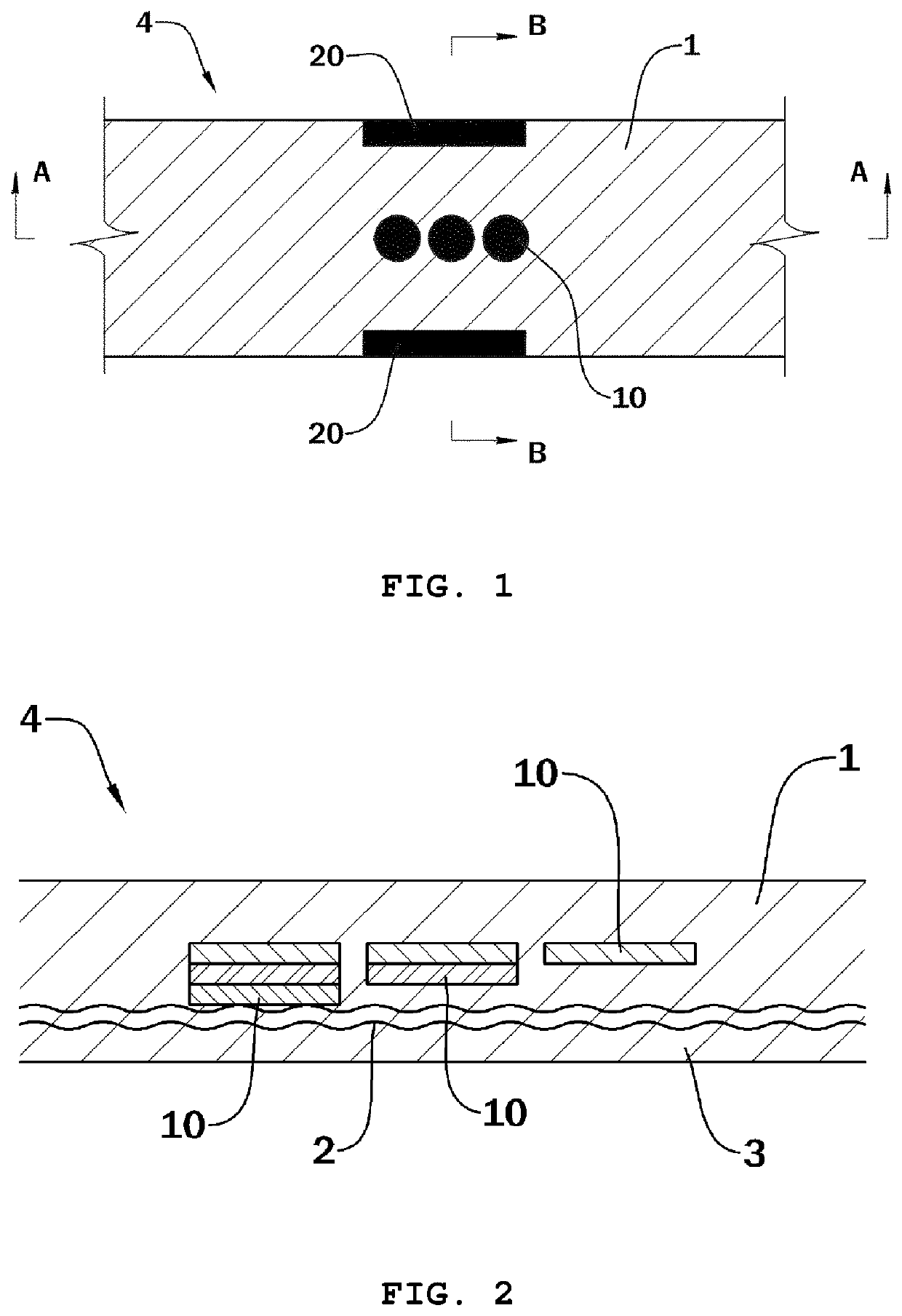
[0014]Embodiments of the present invention provide a conveyor belt for marginal life prediction for checking the wear extents of the conveyor belt visually and easily, and predicting the life time of the conveyor belt well and conveniently, while not stopping the conveyor belt on operation and while contributing to further improve the function of the conveyor belt carrying articles.
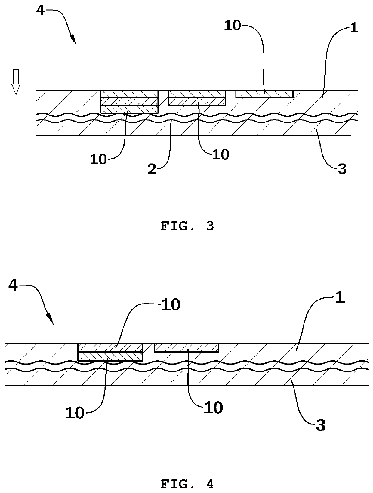
[0016]Further, according to embodiments of the present invention, the abrasion check colored rubbers may be installed in multi-layers with the installation number reduced downwardly, so that the number of the exposed abrasion check colored rubbers is detected and the life time of the conveyor belt can be predicted step by step precisely.
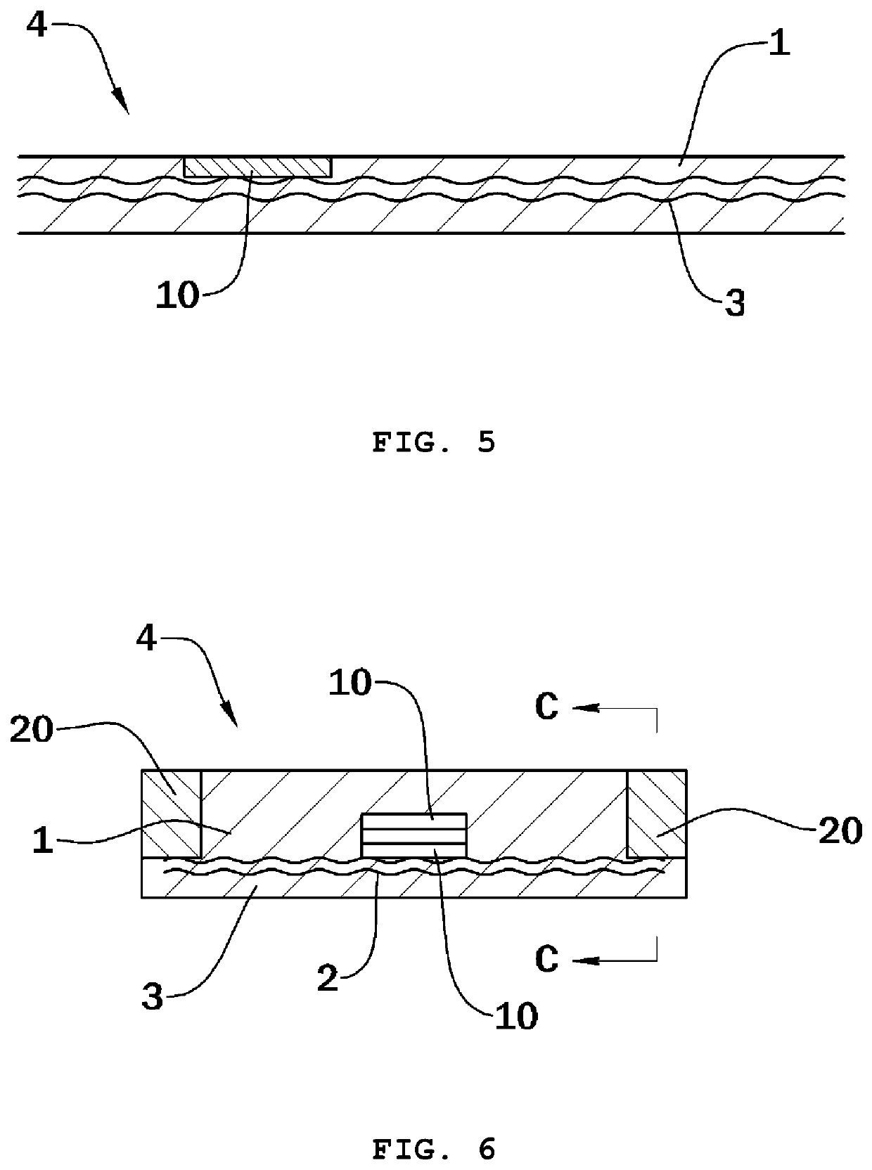
[0017]Further, according to embodiments of the present invention, the abrasion check colored rubbers may be locally formed along the longitudinal direction of the conveyor belt or the widthwise direction thereof, thereby to greatly increase the functional performance of the troughs of the conveyor belt.
[0018]Therefore, according to embodiments of the present invention, since a plurality of abrasion check colored rubbers functioning as abrasion sensor are installed inside the conveyor belt, and anybody can see and know the outwardly-exposed colored rubbers by eyes when the abrasion is proceeded, the abrasion state and extents of the conveyor belt can be checked and its replacement time can be predicted. Further, without necessity of stopping the production lines of the conveyor belt on operation, since the acknowledgement of the abrasion state of the conveyor belt is possible, the production costs can be incredibly saved and the life time of the conveyor belt can be predicted easily and managed simply without other complex measurement devices.
[0019]Further, since the abrasion check colored rubbers of the present invention may be installed in multi-layers so that the number of the colored rubber being installed is reduced downwardly, the life time of the conveyor belt can be predicted step by step by seeing the number of the abrasion check colored rubbers exposed outwardly, and it is very convenient and efficient to prepare a new conveyor belt for replacement in time and the replacement time of the conveyor belt can be reduced radically and saved greatly.
[0020]Further, since the abrasion check colored rubbers of the present invention may be installed locally along the longitudinal direction or the widthwise direction, the troughs of the conveyor belt can be formed greatly and well and the entire function of the troughs can be radically improved because of big angle of the trough, thereby to provide the effect and the result of carrying articles more efficiently and well on the conveyor belt and preventing the occurrence of the articles deviated out of the conveyor belt in advance.

Problems solved by technology

Such a conveyor belt for carrying is worn out necessarily by the abrasion with carrying articles.
In order to measure even the thickness of the worn conveyor belt, it is necessary to stop the conveyor line on operation, and use a vernier caliper which is specifically manufactured, or use an ultrasonic equipment which is high expensive but incorrect in precision.
The conveyor line as above is very dangerous structurally for a worker to access or very difficult to measure the thickness of the belt according to the characteristics of the transported objects (kinds, size, amount).
Specifically, since it was difficult to visually see and check the abrasion extents of the conveyor belt by eyes, and impossible to find out the replacement time of the conveyor belt or the repair time thereof in time, there was a problem remained that the management of the conveyor belt equipment was not implemented properly.
The conveyor belt of the related art of technology as above has a problem in that the colored layer for abrasion check is formed just as one single layer, and it just provides with the confirm of the conveyor belt being worn out, and thus, it is not efficient to prepare a new conveyor belt for replacement in advance in time, because it is difficult to check the abrasion extent properly by steps and predict the life time of the conveyor belt.
Further, since the colored layer for abrasion check is formed entirely on the conveyor belt in the longitudinal and widthwise directions, the formation of troughs is not properly made, and the angle of the trough is so small that there often occurs the problem that transported articles are easily released and fallen down out of the conveyor belt.

Method used


Image

  • Conveyor belt for marginal life prediction
  • Conveyor belt for marginal life prediction
  • Conveyor belt for marginal life prediction

Examples


Embodiment Construction

[0031]Since exemplary embodiments of the present invention are provided only for structural and functional descriptions of the present invention, the present invention should not be construed as limited to the embodiments set forth herein. Thus, it will be clearly understood by those skilled in the art that the exemplary embodiments of the present invention may be embodied in different forms and include equivalents that can realize the spirit of the present invention. It should be understood, however, that it is not intended to limit the present invention to the particular forms disclosed, but on the contrary, the present invention is to cover all modifications, equivalents, and alternatives falling within the spirit and scope of the present invention as defined by the appended claims.

[0032]The terminology used herein is for the purpose of describing particular embodiments only and is not intended to be limiting of the present invention. As used herein, the singular forms “a”, “an” ...


PUM

PropertyMeasurementUnit
thicknessaaaaaaaaaa
thicknessaaaaaaaaaa
thicknessaaaaaaaaaa

Abstract

There is provided a conveyor belt for marginal life prediction, in which wear of the degree of the conveyor belt can be well and visually recognized without stopping of the conveyor belt on operation, and the replacement time of the conveyor belt can be easily predicted in advance, thereby to predict and efficiently manage the life time of the conveyor belt. It was difficult to check abrasion extents step by step and exactly predict the life time in the conventional conveyor belts. Further, the accidents of carrying articles released out of the conveyor belt were frequently occurred since troughs of the conveyor belt are not formed enough, and the angle of the trough is so small. As the way of solving the problems as above, while the wear of the conveyor belt is progressed, and when the abrasion check colored rubbers, which are embedded inside the conveyor belt, are exposed outwardly and checked visually by eyes, the extent of the abrasion of the conveyor belt can be estimated and the exchange time of the conveyor belt can be well predicted. The number of the exposed abrasion check colored rubbers is well detected by installing the abrasion check colored rubbers in multi-layers with installation number reduced downwardly, thereby to enable anybody to predict the life time of the conveyor belt step by step precisely.

Description

BACKGROUND1. Field[0001]Embodiments of the present invention relate to a conveyor belt for marginal life prediction, and more particularly, to a conveyor belt for marginal life prediction for informing the replacement time of the conveyor belt in advance while allowing anybody to easily and visually know the abrasion extents of the conveyor belt without stopping of the conveyor belt on operation, and for predicting and managing the life time of the conveyor belt effectively.2. Description of Related Art[0002]Generally, a conveyor belt is a device operated by circulating a belt which is made of rubber, fabric, wire mesh, steel plate, and so on, and placing various articles on the conveyor belt and carrying them sequentially, and the side shape of the belt is formed as closed curve, and the belt is put on the pulley and is operated by rotating the pulley by electric motor.[0003]Such a conveyor belt for carrying is worn out necessarily by the abrasion with carrying articles. Particular...

Claims


Application Information

Patent Timeline
Patent Type & Authority Patents(United States)
IPC IPC(8): B65G43/02B65G15/34B32B1/00B32B5/02B32B3/30B32B25/04B32B25/10
CPCB65G43/02B32B1/00B32B3/30B32B5/024B32B25/042B32B25/10B65G15/34B32B2250/40B32B2307/4026B32B2433/02B65G2201/045B65G2207/48B32B3/08B32B2250/03B65G15/32B65G2812/02138B65G2812/02198
Inventor KIM, WOOJEONGLIM, O SIKSIM, EUN GUCHOI, IL HOKIM, JAE KWANPARK, JONG UKKIM, SOO HWAN
Owner KIM WOOJEONG
Why Eureka
Try Eureka