
Method of manufacturing a crystalline aluminum-iron-silicon alloy

a technology of iron aluminide and manufacturing method, which is applied in the field of manufacturing method of crystalline aluminumironsilicon alloy, can solve the problems of reduced density of iron aluminide, reduced ductility of iron aluminide,

Active Publication Date: 2021-02-09
GM GLOBAL TECH OPERATIONS LLC
View PDF0 Cites 0 Cited by
  • Summary
  • Abstract
  • Description
  • Claims
  • Application Information

AI Technical Summary

Benefits of technology

[0001]Iron aluminides (e.g., FeAl and Fe3Al) are intermetallic compounds having a defined stoichiometry and an ordered crystal structure. Many iron aluminides exhibit excellent high-temperature oxidation resistance, relatively low densities, high melting points, high strength-to-weight ratios, good wear resistance, ease of processing, and low production cost since they generally do not incorporate rare elements, which makes them attractive substitutes for stainless steel in industrial applications. However, at low to moderate temperatures, iron aluminides oftentimes suffer from poor ductility and low fracture toughness. At elevated temperatures, iron aluminides have been found to exhibit limited creep resistance and high thermal conductivity. Increasing the aluminum content of such materials can decrease their density and enhance the formation of a protective oxide layer at high temperatures, but also may significantly lower their ductility in moisture-containing environments (e.g., air) due to a phenomenon known as hydrogen embrittlement.

Problems solved by technology

However, at low to moderate temperatures, iron aluminides oftentimes suffer from poor ductility and low fracture toughness.
At elevated temperatures, iron aluminides have been found to exhibit limited creep resistance and high thermal conductivity.
Increasing the aluminum content of such materials can decrease their density and enhance the formation of a protective oxide layer at high temperatures, but also may significantly lower their ductility in moisture-containing environments (e.g., air) due to a phenomenon known as hydrogen embrittlement.

Method used


Image

  • Method of manufacturing a crystalline aluminum-iron-silicon alloy
  • Method of manufacturing a crystalline aluminum-iron-silicon alloy

Examples


examples

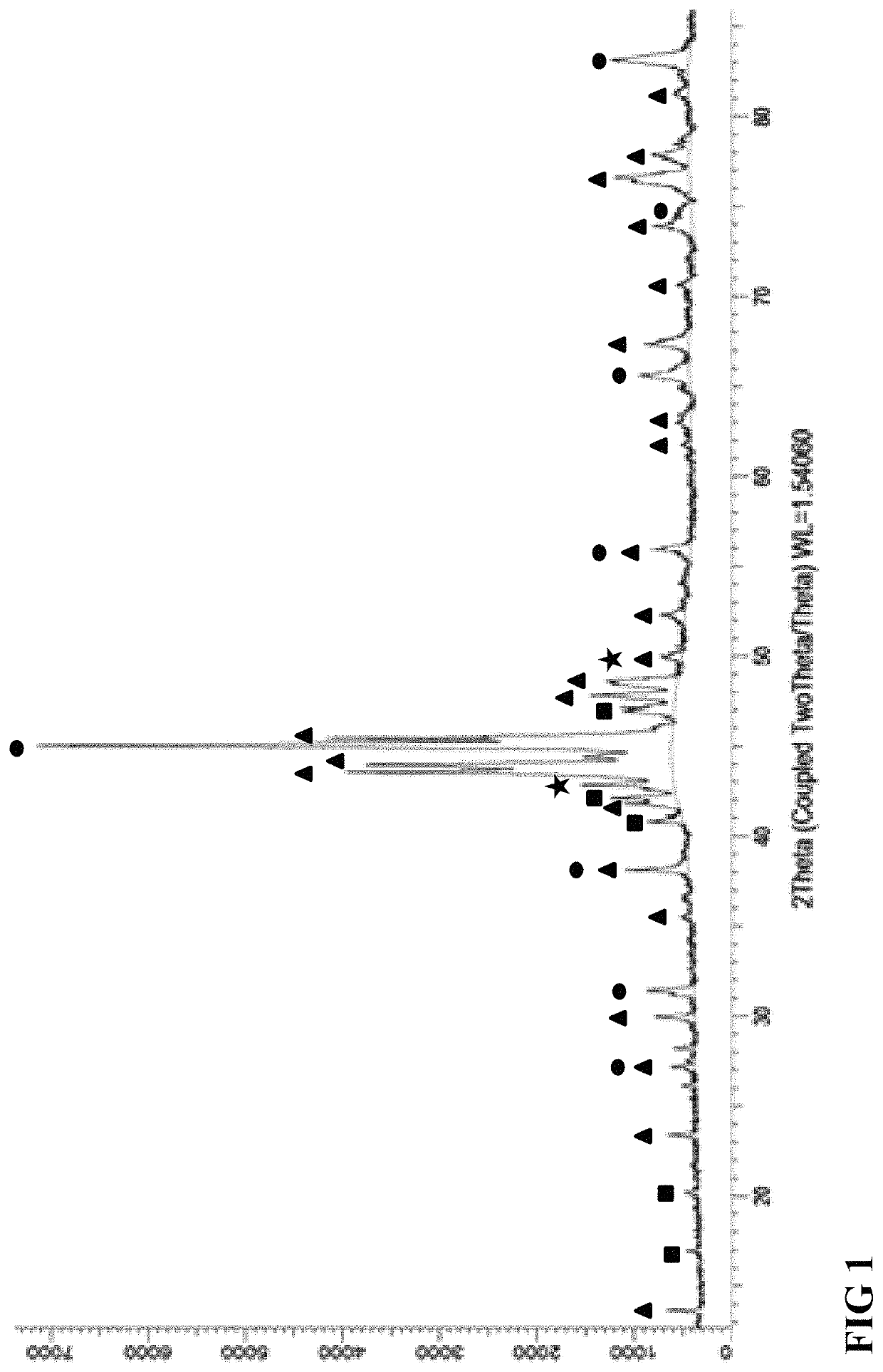
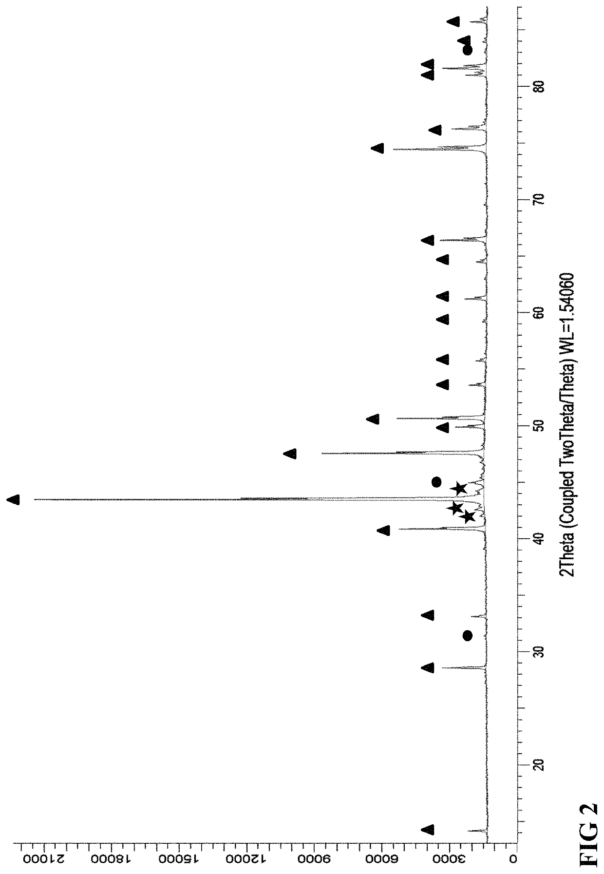
[0029]Aluminum, iron, and silicon raw materials were combined to form a 400 g melt comprising 35% aluminum, 53% iron, and 12% silicon. The raw materials were melted at 1200° C. for 5 minutes to form a cylindrical composite ingot approximately 3.8 cm in diameter and 7.7 cm in height. X-ray diffraction (XRD) was performed on the resulting composite ingot using a D8-Advance Davinci diffractometer in a Bragg Brentano configuration using copper Kα radiation. Data was collected from 10°-90° 2θ using a 0.02° step size and an integration time of 1 sec / step. Rietveld refinement was performed using DIFFRAC. SUITE TOPAS software. FIG. 1 illustrates an XRD pattern of the as-prepared composite ingot. The XRD pattern of the as-prepared composite ingot indicates a composition of about 72% Fe1.7Al4Si hexagonal (P63 / mmc) crystalline phase (indicated by triangles in FIG. 1), about 23% Fe3Al0.25Si0.75 cubic (Fm-3m) crystalline phase (indicated by circles in FIG. 1), about 5% Fe3Al Cubic (Pm-3m) crysta...


PUM

PropertyMeasurementUnit
temperatureaaaaaaaaaa
pressuresaaaaaaaaaa

Abstract

Provided is a method of manufacturing a crystalline aluminum-iron-silicon alloy, and optionally an automotive component comprising the same, comprising forming a composite ingot including a plurality of crystalline phases by melting aluminum, iron, and silicon raw materials in an inert environment to form a substantially homogenous melt, subsequently solidifying the melt, and annealing the ingot under vacuum by heating at a temperature in the range of 850° C. to 1000° C. yield an annealed crystalline ingot wherein the predominant crystalline phase is FCC Al3Fe2Si. The raw materials can further include one or more additives such as zinc, zirconium, tin, and chromium. Melting can occur above the FCC Al3Fe2Si crystalline phase melting point, or at a temperature of about 1100° C. to about 1400° C. Annealing can occur under vacuum conditions.

Description

INTRODUCTION[0001]Iron aluminides (e.g., FeAl and Fe3Al) are intermetallic compounds having a defined stoichiometry and an ordered crystal structure. Many iron aluminides exhibit excellent high-temperature oxidation resistance, relatively low densities, high melting points, high strength-to-weight ratios, good wear resistance, ease of processing, and low production cost since they generally do not incorporate rare elements, which makes them attractive substitutes for stainless steel in industrial applications. However, at low to moderate temperatures, iron aluminides oftentimes suffer from poor ductility and low fracture toughness. At elevated temperatures, iron aluminides have been found to exhibit limited creep resistance and high thermal conductivity. Increasing the aluminum content of such materials can decrease their density and enhance the formation of a protective oxide layer at high temperatures, but also may significantly lower their ductility in moisture-containing environ...

Claims


Application Information

Patent Timeline
Patent Type & Authority Patents(United States)
IPC IPC(8): C22C33/04C22C33/00C22C38/06C22C38/02C21D6/00
CPCC22C33/04C21D6/008C22C33/006C22C38/02C22C38/06C22C2200/00C22C21/00C22C30/00C22F1/04C21D1/26
Inventor LIU, ZHONGYIQI, TENGJIAOSALVADOR, JAMES R.KUKREJA, RATANDEEP S.
Owner GM GLOBAL TECH OPERATIONS LLC
Learn More