Valve apparatus for influencing a flow of medium

Active Publication Date: 2021-02-09
HYDAC SYST & SERVICES GMBH
View PDF4 Cites 0 Cited by
  • Summary
  • Abstract
  • Description
  • Claims
  • Application Information

AI Technical Summary

Benefits of technology

[0005]Based on this prior art, the invention therefore addresses the problem of further improving this known solution in that the operating behavior in regard to regulation is improved in a cost-

Problems solved by technology

The dimensioning of the bores has to be as accurate as possible to perform the actuation, resulting in high production cost.
It has also been shown in practice that, due to the relatively narrowly dimensioned free duct cross-sections of the control duct mentioned, problems can occur in the immediate transmission of the hydr

Method used


Image

  • Valve apparatus for influencing a flow of medium
  • Valve apparatus for influencing a flow of medium
  • Valve apparatus for influencing a flow of medium

Examples


Example

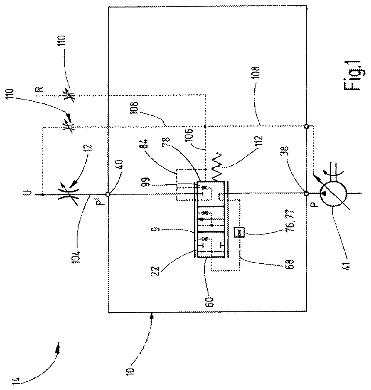
[0023]FIG. 1 shows in the form of a hydraulic symbol or schematic diagram of a pressure maintenance component 9 in conjunction with a metering aperture 12, which in the overall function form a volume flow regulator 14 having the valve device according to the invention having the valve or valve device 10. The essential components of valve 10 are combined in a frame-like block representation

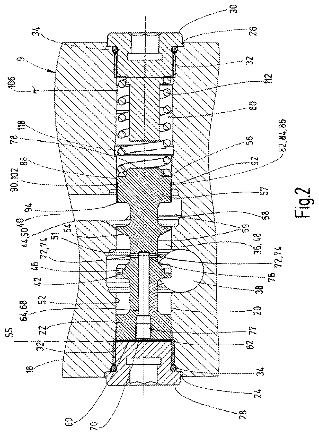
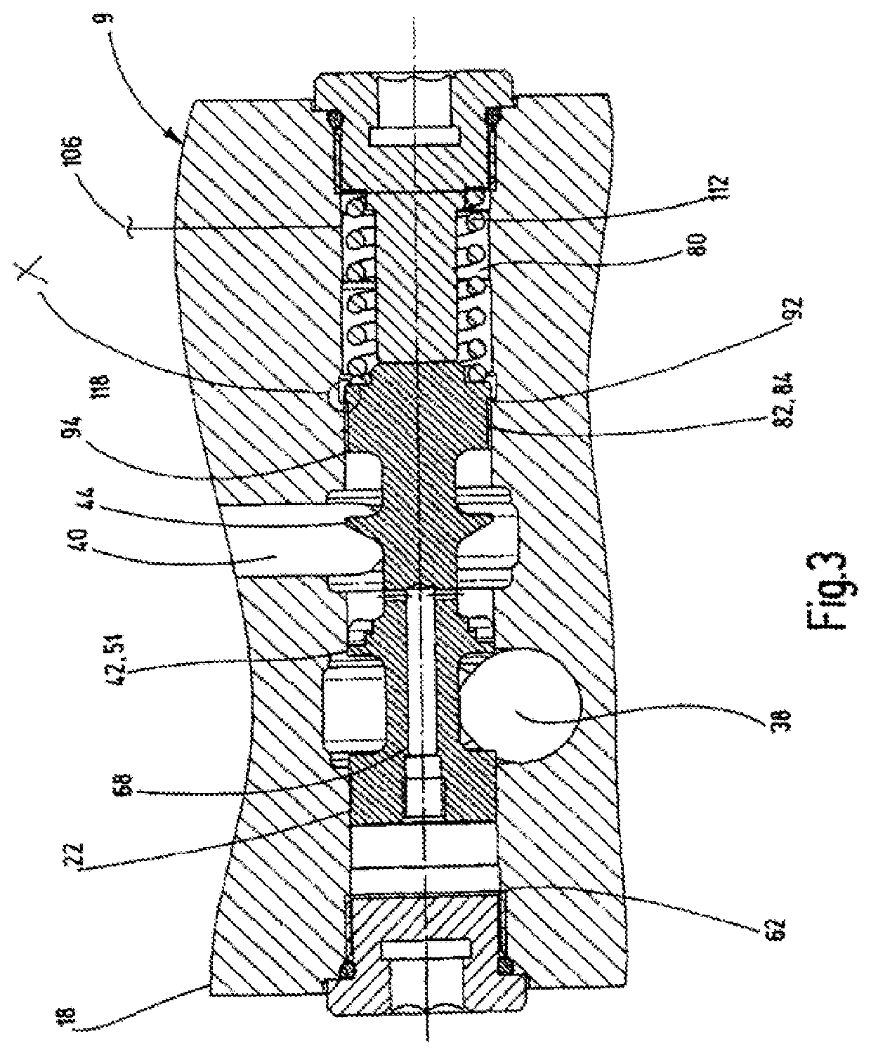
[0024]According to the longitudinal sectional views of FIGS. 2 and 3, a valve housing 18 has a valve bore 20, in which a longitudinally movable guided valve spool 22 is arranged. The valve bore 20 is closed at both ends 24, 26 by cap screws 28, 30, which each engage in an assignable female thread 32 of the valve bore 20. Annular sealing elements 34 are provided between the cap screws 28, 30 and the valve housing 18.

[0025]The valve spool 22 is provided for controlling a fluid-conveying connection 36 between at least two fluid connection points 38, 40 mounted in the valve housing 18, a supply port 38...


PUM


Abstract

A valve apparatus for influencing a flow of medium between a supply port (38) and a pressure port (40) has a valve device (10). In one closed position, the valve device blocks the connection between the supply port (38) and the pressure port (40). The valve device opens this connection in one opened position, in which the pressure port (40) is connected to at least one of two medium chambers (62, 80) by a respective fluid channel (64, 82). One fluid chamber (64) comprises a fluid duct (68) in the valve slider (22). The other fluid channel (82) has a further fluid duct (84) that is separate from the fluid duct (68). In one of the opened positions of the valve slider (22), the further fluid duct (84) opens at one end (92) into the medium chamber (80). In every displacement position of the valve slider (22), the further fluid duct (84) is permanently connected at the other end (94) to the pressure port (40).

Description

FIELD OF THE INVENTION[0001]The invention relates to a valve device for influencing a media flow between a supply port to which a pressure supply source can be connected. A pressure port can be connected to a hydraulic consumer. The valve device has a valve spool, which is guided in axial travel directions within a valve housing. The opposite end faces of the valve housing at least partially delimit two media chambers within the valve housing. The valve device blocks the connection between the supply and the pressure port in at least one closed position which opens that connection in at least one of its open positions, in which the pressure port is connected to at least one of two media chambers via a relevant fluid guide. One fluid guide is formed of a valve spool located in the fluid duct, one end of which opens into a media chamber and the other end of which opens into a fluid chamber in the valve housing. The fluid chamber is separated from the pressure port in the at least one ...

Claims


Application Information

Patent Timeline
IPC IPC(8): F15B13/02F15B13/04F15B13/00
CPCF15B13/026F15B13/0402F15B13/0417F15B2013/008
Inventor BIWERSI, SASCHA ALEXANDER
Owner HYDAC SYST & SERVICES GMBH
Why Eureka
Try Eureka