Method for moving to a reference feed position of a label tape and device for labelling containers

a technology of reference feed position and label tape, which is applied in the field of method and system for labelling containers, can solve the problems of inability to adjust the exact angle of the pusher roller system, the impact of the arm or carriage carrying the pusher roller is elastically damped at the adjustment limit, and the inability to add additional thrust roller systems, etc., to achieve the effect of simplifying the precise positioning of the label tape and the inability to alter the length of the conveyor section

Active Publication Date: 2021-02-23
KRONES AG
View PDF13 Cites 0 Cited by
  • Summary
  • Abstract
  • Description
  • Claims
  • Application Information

AI Technical Summary

Benefits of technology

[0013]This eliminates the cumbersome handling of labels at the dispensing edge when moving to a reference feed position by unwinding the label tape from its supply roller. In addition, label tapes of different thicknesses and / or with different mechanical properties may be easily wound back onto their supply rollers and then moved to the reference feed position under tension. No actively driven conveyor roller system between the supply roller and the dispensing edge is required to move to the reference feed position.
[0015]After reaching the adjustment limit, the conveying distance between the supply roller and the dispensing edge has a constant length. In other words, the length of the conveyor section cannot be altered by unwanted changes in the size of the loop buffer when setting the reference feed position, though it may be altered by other means. At the lower adjustment limit of the buffer size, the distance between the supply roller and the dispensing edge is known by design. This simplifies precise positioning of the label tape.
[0016]In other aspects, the actual feed position of the label tape is monitored by sensors, and conveyance of the previously rewound label tape in the normal feed direction beyond the actual feed position is automatically stopped as soon as the actual feed position for at least one label of the label tape matches the reference feed position. This allows the reference feed position to be automatically and precisely moved.
[0017]In a further aspect, the actual feed position between the dispensing edge and loop buffer is monitored. This enables a precise determination of the actual feed position and a correspondingly precise move to the reference feed position. An alternative or supplementary monitoring through the use of sensors of the actual feed position between loop buffer and supply roller is also contemplated.
[0018]In some aspects, when the buffer is discharged, at least one movable buffer roller of the loop buffer is shifted and / or swivelled to an adjustment limit against an elastic pre-tension. In labelling operation, the elastic pre-tensioning serves to produce a predetermined tape tension upstream of the dispensing edge. After moving and / or swivelling the buffer roller to the adjustment limit, a higher tape tension may be produced upstream of the dispensing edge than would be possible in normal labelling operation using the elastic pre-tension. In addition, the length of the label tape in the loop buffer is constant and known by design after reaching the lower adjustment limit.
[0019]In additional aspects, the adjustment movement of the buffer roller is elastically damped in the area of the adjustment limit. This means that the impact of an arm or carriage carrying the buffer roller is elastically damped at the adjustment limit. Alternatively, the buffer roller may be elastically deformable, e.g. made of an elastic material, or elastically supported. This prevents abrupt changes in tape tension when the adjustment limit is reached. This protects the label tape and promotes a continuous rewinding of the label tape both before and after reaching the lower adjustment limit.

Problems solved by technology

The disadvantage, however, is that such pusher roller systems must be adjusted exactly to the thickness and / or material of the label tape to be transported.
Such transport systems are therefore only conditionally suitable for flexible labelling with different label tapes.
This means that the impact of an arm or carriage carrying the buffer roller is elastically damped at the adjustment limit.
In some aspects, additional thrust roller systems are unnecessary.

Method used


Image

  • Method for moving to a reference feed position of a label tape and device for labelling containers

Examples


Embodiment Construction

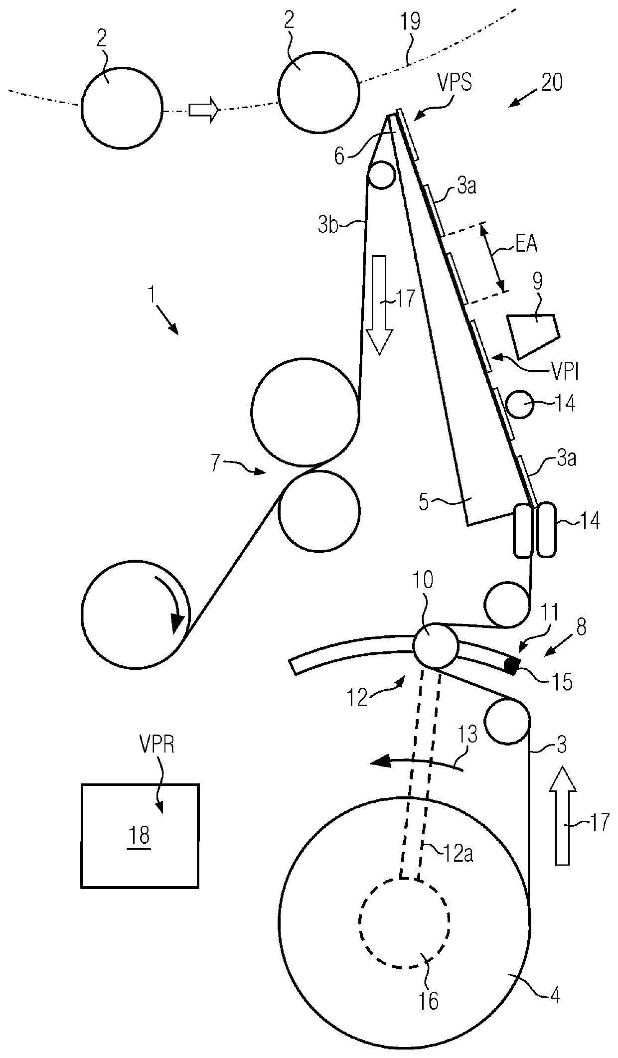
[0034]Downstream of the dispensing edge 6, a roller system 7 is configured for drawing the label tape 3 in the normal feed direction 17 around the dispensing edge 6. The liner 3b of the label tape 3 thus runs under tension through the roller system 7 and is wound up behind the roller system in the usual manner for disposal.

[0035]Between the supply roller 4 and the dispensing edge 6, a loop buffer 8 is arranged. Between the loop buffer 8 and the dispensing edge 6 a feed sensor 9 is arranged for monitoring an actual feed position (labelled VPI in FIG. 1) of the label tape 3 with respect to the dispensing edge 6.

[0036]For example, the feed sensor 9 is an ultrasonic sensor, an optical contrast sensor, an optical print mark sensor, a line scan camera or the like. The feed sensor 9 detects the actual feed position (VPI) of individual labels 3a, for example by means of separate print marks on the label tape 3 and / or by printing the labels 3a.

[0037]Loop buffer 8 comprises at least one mova...


PUM

PropertyMeasurementUnit
sizeaaaaaaaaaa
elastic pre-tensionaaaaaaaaaa
movementaaaaaaaaaa

Abstract

A method for moving to a reference feed position of a label tape with respect to a dispensing edge of a container labeller and a corresponding device is described. The label tape may be first pulled back beyond the reference feed position by rewinding to its supply roller and then conveyed in the normal feed direction to the reference feed position prevents unwanted detachment of labels at the dispensing edge as a result of the label tape unwinding from the supply roller as well as the use of pusher roller systems upstream of the dispensing edge.

Description

CROSS REFERENCE TO RELATED APPLICATION[0001]This application claims priority to German Patent Application No. 10 2017 215 757.7 entitled “METHOD FOR MOVING TO A REFERENCE FEED POSITION OF A LABEL TAPE AND DEVICE FOR LABELLING CONTAINERS,” filed on Sep. 7, 2017, the entire contents of which is hereby incorporated by reference in its entirety for all purposes.TECHNICAL FIELD[0002]The present disclosure relates to methods and systems for labelling containers.BACKGROUND AND SUMMARY[0003]For the labelling of containers, it is known that a label tape, in which self-adhesive labels are arranged on a liner at regular intervals from each other, is guided around a dispensing edge in the area of the containers so that the labels can be detached from the liner at the dispensing edge and transferred to the containers. For this purpose, the containers are transported on a carousel or along a linear conveyor section of a labeller. The dispensing edge is preferably arranged at the free end of a boo...

Claims


Application Information

Patent Timeline
Patent Type & Authority Patents(United States)
IPC IPC(8): B32B41/00B65C9/18B65C1/02B65C9/00B65C9/02B65C9/42
CPCB65C9/1865B65C1/02B65C9/0006B65C9/02B65C9/42
Inventor HÖGL, BERNHARD
Owner KRONES AG
Why Eureka
Try Eureka