Pre-charging circuitry for multiplexer

a multi-channel amplifier and circuit technology, applied in the direction of electronic switching, pulse technique, transportation and packaging, etc., can solve the problems of limiting the switching time and circuit throughput of the mux channel, the charge flow is not instantaneous, and the level shifting burden of the amplifier, so as to reduce the level shifting burden. , the effect of stable and low-power operation

Active Publication Date: 2021-02-23
ANALOG DEVICES INT UNLTD
View PDF10 Cites 4 Cited by
  • Summary
  • Abstract
  • Description
  • Claims
  • Application Information

AI Technical Summary

Benefits of technology

[0003]In some examples of the present disclosure a pre-charge circuit is provided for pre-charging the input node of a capacitive component to which the multiplexer output is fed to a charge level that is close to or approximates the signal output level of the multiplexer when its output is next switched. In order to reduce the level shifting burden on the amplifier in the pre-charge circuit, each pre-charge circuit input channel has a respective capacitor that is able to be switched in and out of series with the respective multiplexer channels, such that the respective capacitors track the signal levels on the respective channels. The provision of the corresponding capacitors for each MUX channel reduces the input current to the pre-charge amplifier, and allows for the level shifting burden to be taken by the capacitors, leading to more stable and lower power operation.
[0004]In view of the above, an example described herein provides a multiplexing circuit having pre-charge circuitry for pre-charging a capacitive load to which a multiplexer provides a signal. The multiplexing circuit may comprise a multiplexer having a plurality of input channels and an output channel, a capacitive load connectable to the output channel of the multiplexer, and pre-charge circuitry arranged in use to pre-charge the capacitive load in dependence on a signal on one of the input channels to the multiplexer to be next output to the capacitive load. The pre-charge circuitry may further comprise a first amplifier arranged to provide a first pre-charging signal to the capacitive load to pre-charge the load, a plurality of capacitors switchable so as to track respectively the plurality of input channels to the multiplexer, and first switching circuitry controllable to switch into series with the first amplifier input the respective capacitor that tracks the input channel to the multiplexer to be next output. As noted above, the provision of the capacitors means that the first amplifier does not need to deal with as great signal level changes as would otherwise be the case, leading to stable and power efficient operation.
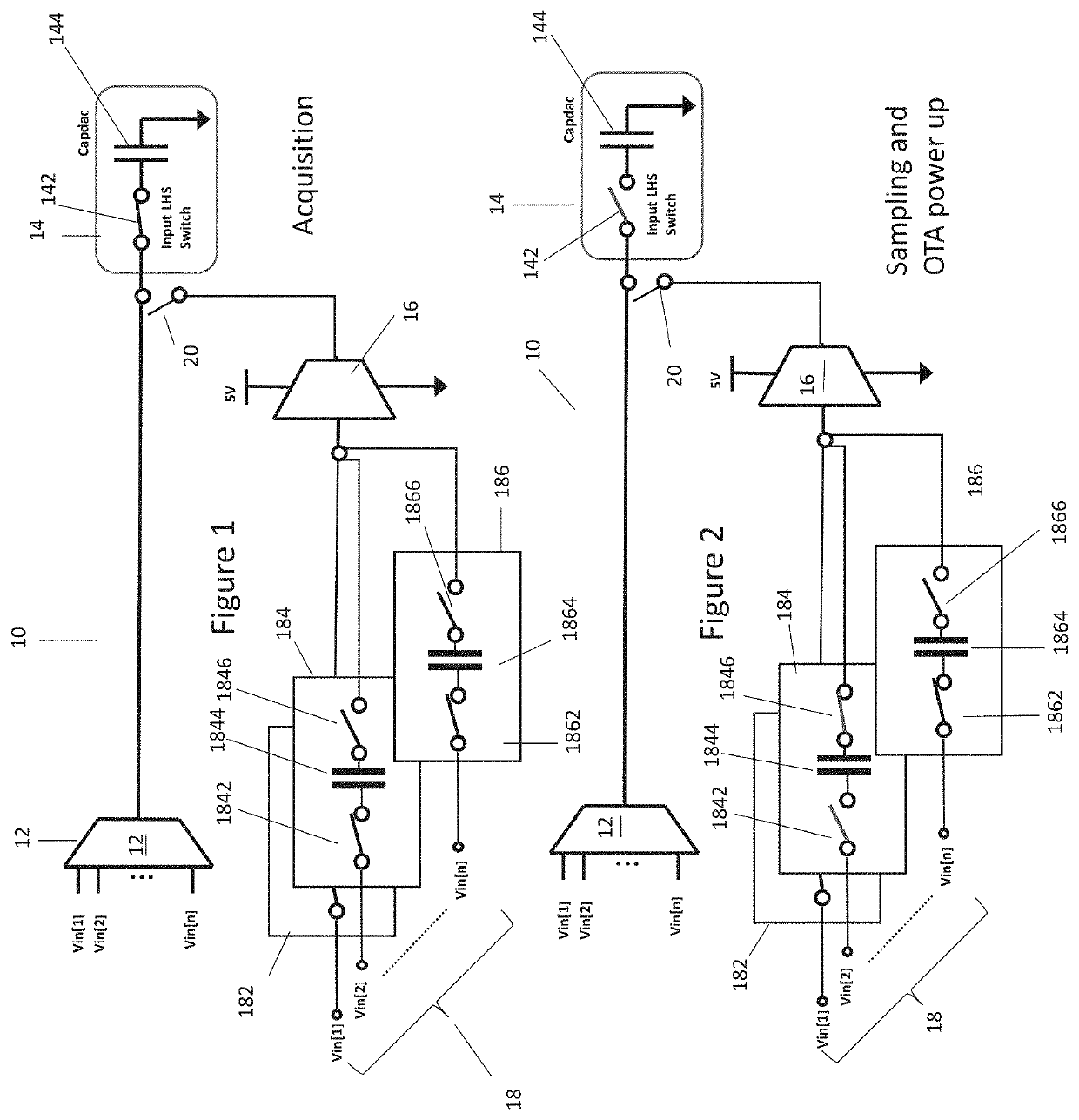
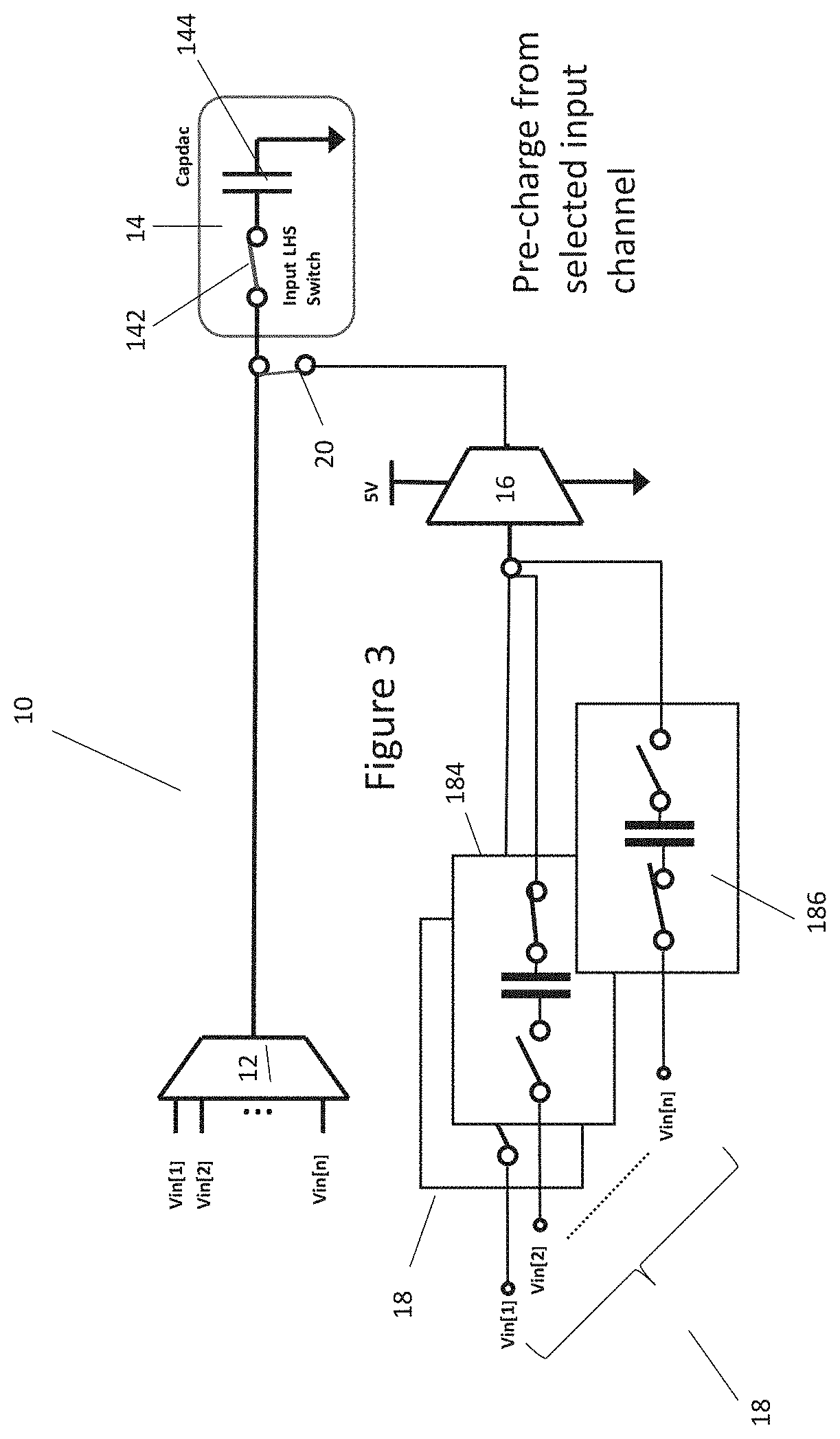
[0006]In a further example, two or more capacitors are provided respectively per input channel to the multiplexer, the two or more capacitors per channel being switchable so as to track respectively the input channels of the multiplexer. The provision of two capacitors per channel allows the next input channel to be output by the multiplexer to be tracked all the way through the pre-charging phase, so that the pre-charge may be as accurate as possible.
[0007]In an example where two capacitors are provided, the first amplifier is a differential amplifier having respective first and second differential inputs, one of the two or more capacitors per input channel being connectable via the switching circuitry between the respective multiplexer input channel for the capacitor and the first differential input of the first amplifier, and the other of the two or more capacitors being connectable via the switching circuitry between: i) in a first phase of operation, the respective multiplexer input channel for the capacitor; or ii) in a second phase of operation, the multiplexer output channel; and the second differential input of the first amplifier. As noted above, the connections of such capacitors allows one of the capacitors to track the next input node to be output by the MUX throughout the pre-charge phase, whilst the other capacitor senses the charge on the MUX output line, thereby permitting accurate control of the charge supplied by the first amplifier.
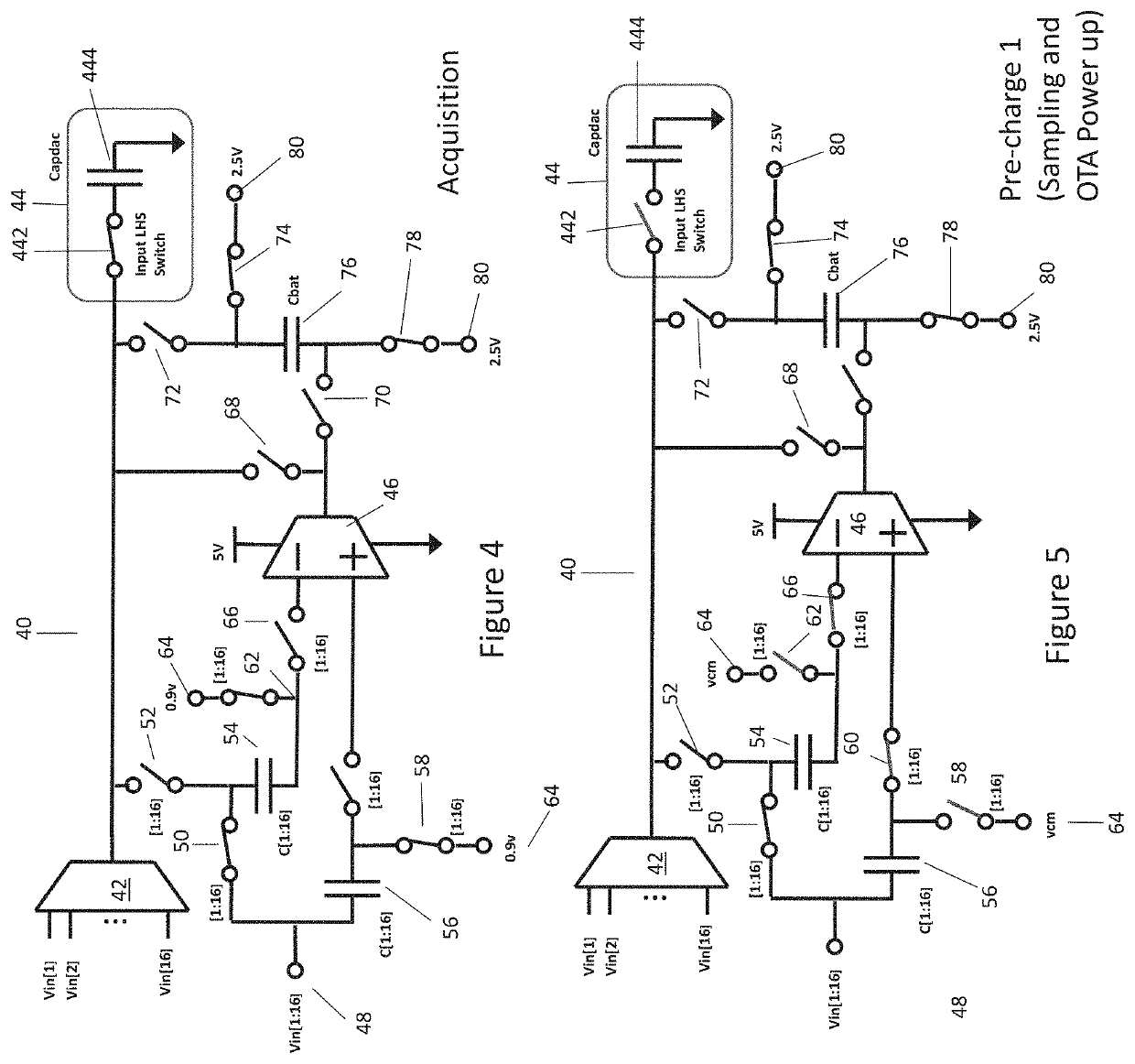
[0016]In another example described herein there is also provided a further multiplexing circuit having pre-charge circuitry for pre-charging a capacitive load to which a multiplexer provides a signal. In this example the pre-charge circuitry further comprises a first amplifier arranged to provide a first pre-charging signal to the capacitive load to pre-charge the load, and a battery capacitor switchable into series between the output of the first amplifier and the capacitive load to provide a top-up pre-charging signal to the capacitive load. As explained previously in respect of an earlier example, the provision of a battery capacitor helps the first amplifier to pre-charge the capacitive load to levels that may be at or near to the supply voltage rails of the amplifier, and that otherwise the amplifier may find difficult to achieve in a timely fashion on its own.

Problems solved by technology

This flow of charge is not instantaneous and takes a finite amount of time, limiting MUX channel switching times and circuit throughput.
However, such amplifiers can experience operational difficulties in having to deal with the full range of possible input signals that may be present on different MUX channels, in that they may not be capable of fast-enough rail to rail output level shifting, or be able to drive the capacitive node through rail to rail voltage ranges.

Method used


Image

  • Pre-charging circuitry for multiplexer
  • Pre-charging circuitry for multiplexer
  • Pre-charging circuitry for multiplexer

Examples


Embodiment Construction

[0037]In an example of the present disclosure a pre-charge circuit is provided that is intended to pre-charge the input node of a capacitive component to which the multiplexer output is fed (or alternatively the output node of the multiplexer, where it is different) to a charge level that is close to or approximates the signal output level of the multiplexer when its output is next switched. In order to reduce the level shifting burden on the amplifier in the pre-charge circuit, the pre-charge circuit is provided with a corresponding number of input channels to the number of MUX channels, with the pre-charge circuit input channels being connected to the same input nodes as the input channels of the MUX, such that the same respective signals Vin[1], Vin[2], . . . , Vin[n] appear thereon. Each pre-charge circuit input channel has a respective capacitor that is able to be switched in and out of series with the respective input node, such that the respective capacitors track the signal ...


PUM


Abstract

A pre-charge circuit is provided for pre-charging the input node of a capacitive component to which the multiplexer output is fed to a charge level that is close to or approximates the signal output level of the multiplexer when its output is next switched. In order to reduce the level shifting burden on the amplifier in the pre-charge circuit, each pre-charge circuit input channel has a respective capacitor that is able to be switched in and out of series with the respective multiplexer channels, such that the respective capacitors track the signal levels on the multiplexer channels. The provision of the corresponding capacitors for each MUX channel reduces the input current to the pre-charge amplifier, and allows for the level shifting burden to be taken by the capacitors, leading to more stable and lower power operation.

Description

FIELD OF THE DISCLOSURE[0001]The present disclosure relates to a pre-charging circuit that pre-charges a capacitive node to which the output of a multiplexer is to be switched to allow faster charge settling times at the capacitive node after multiplexer channel switching has occurred.BACKGROUND[0002]When the output of a multiplexer (MUX) is switched so as to be connected to a capacitive node (such as the input node of a switched capacitor digital-to-analog converter (DAC) that forms part of an analog-to-digital converter (ADC)), charge redistribution may need to occur to drive the capacitive node to be the same voltage as the output of the MUX. For example if the capacitive node was connected in an immediately previous MUX cycle to a MUX channel having a low voltage output signal, and the MUX then switches so as to output a MUX channel having a high voltage output to the capacitive node, electrical charge must flow from the MUX output to the capacitive node to charge the capacitive...

Claims


Application Information

Patent Timeline
Patent Type & Authority Patents(United States)
IPC IPC(8): H03K17/693H03K17/00H03K17/0416H02J7/00H02J7/34
CPCH02J7/0013H02J7/345H03K17/005H03K17/0416H03K17/693H03K17/56
Inventor HURRELL, CHRISTOPHER PETERRAJASEKHAR, SANJAY
Owner ANALOG DEVICES INT UNLTD
Why Eureka
Try Eureka