Seal assembly, roller bearing comprising such an assembly, and method for manufacturing this assembly

a technology of roller bearings and seals, applied in the direction of mechanical equipment, rotary machine parts, transportation and packaging, etc., can solve the problems of increasing friction, rotational frictional torque, mechanical energy loss, etc., and achieve excellent sealing, reduce frictional torque, and improve seal assemblies

Active Publication Date: 2021-03-02
HUTCHINSON SA
View PDF15 Cites 1 Cited by
  • Summary
  • Abstract
  • Description
  • Claims
  • Application Information

AI Technical Summary

Benefits of technology

[0011]The goal of the present invention is to improve seal assemblies of this type, in particular for reducing the frictional torque while retaining an excellent seal.
[0016]These arrangements also have the effect of reducing the wear of the contact surfaces and in particular the seal, and increasing the life of the seal assembly.
[0017]These arrangements also have the effect of maintaining the seal performance and improving the repeatability of this seal performance over a plurality of parts.
[0037]a polishing substep for at least partially eliminating the peaks on the sliding surface.

Problems solved by technology

Unfortunately, this seal assembly contributes to increasing the friction, meaning the rotational frictional torque.
This phenomenon is one part of the mechanical energy losses during rotation.

Method used


Image

  • Seal assembly, roller bearing comprising such an assembly, and method for manufacturing this assembly
  • Seal assembly, roller bearing comprising such an assembly, and method for manufacturing this assembly
  • Seal assembly, roller bearing comprising such an assembly, and method for manufacturing this assembly

Examples


first embodiment

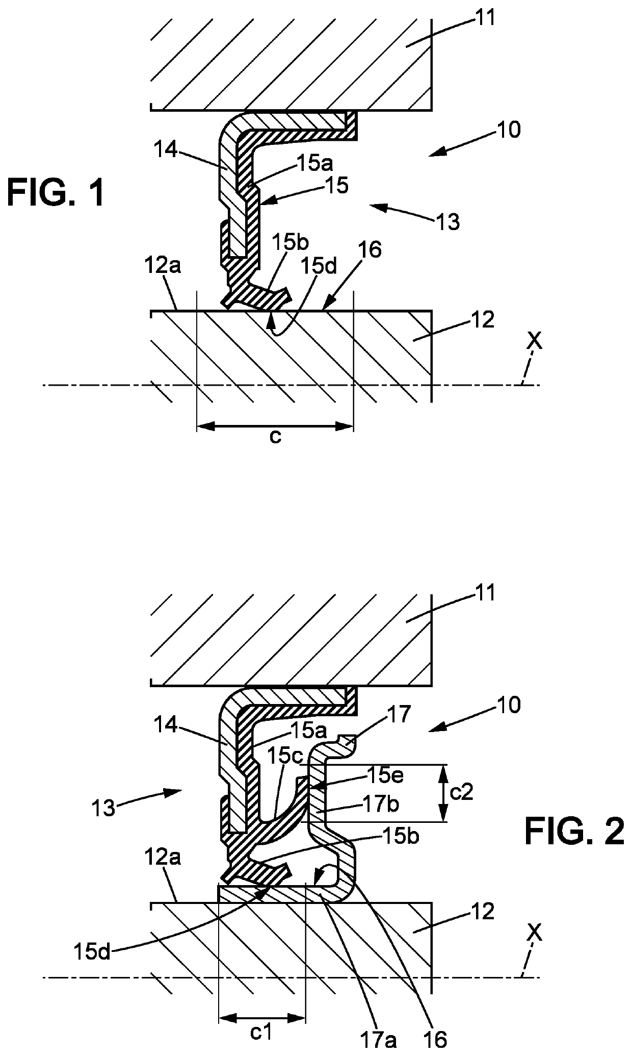
[0051]FIG. 1 shows a seal assembly 10 which comprises:[0052]a fixed element 11;[0053]a rotating element 12 rotatable relative to the fixed element around an axis of rotation X; and[0054]a seal member 13 comprising a stiff annular reinforcement 14 and a seal 15 secured to the reinforcement, where said seal 15 is made of an elastic material and is in contact with the sliding surface 16.

[0055]The reinforcement 14 is mounted securely on one element among the fixed element 11 and the rotating element 12.

[0056]The sliding surface 16 is connected to the other element among the fixed element 11 and the rotating element 12.

[0057]In particular, the fixed element 11 can be an outer element, i.e. farthest from the axis of rotation X, i.e. located around the rotating element 12 which is then an inner element. This is the case of using a rotating element 12 which is a turning shaft (FIG. 1).

[0058]On the other hand, the fixed element 11 can be an inner element, i.e. closest to the axis of rotation...

second embodiment

[0072]FIG. 2 shows the seal assembly 10 which comprises the same elements as the seal assembly from FIG. 1.

[0073]The seal assembly 10 further comprises an annular ring 17 which is secured to the rotating element 12 and which is located between the rotating element 12 and the seal 15. The lip end 15d of the seal 15 is in sliding type contact with at least one surface of this ring which turns with the rotating element 12.

[0074]In the second embodiment, more specifically, the annular ring 17 comprises:[0075]a cylindrical portion 17a mounted securely to the rotating element 12, for example by tightened fitting on the cylindrical surface 12a of said rotating element 12; and[0076]a flange portion 17b which extends from one end of said cylindrical portion 17b radially relative to the axis of rotation X.

[0077]The seal 15 comprises, as in the first embodiment from FIG. 1:[0078]an attachment portion 15a which is attached to at least one reinforcement surface 14; and[0079]a first lip 15b which...


PUM

PropertyMeasurementUnit
arithmetic mean roughnessaaaaaaaaaa

Abstract

The seal assembly comprising a fixed element, a rotating element, and a seal member comprising a stiff annular reinforcement and a seal of an elastic material and in contact with a sliding surface. The sliding surface has an arithmetic mean roughness greater than or equal to 0.15 μm and less than 0.5 μm. The sliding surface has a roughness ratio greater than or equal to one. The roughness ratio is the ratio of a first parameter corresponding to a quantity of valleys to a second parameter corresponding to a quantity of peaks over the sliding surface.

Description

CROSS-REFERENCE TO RELATED APPLICATION[0001]This Application is a 35 USC § 371 US National Stage filing of International Application No. PCT / FR2016 / 052933 filed on Nov. 10, 2016.FIELD OF THE DISCLOSURE[0002]The present invention relates to seal assemblies.BACKGROUND OF THE DISCLOSURE[0003]More specifically, the invention relates to a seal assembly comprising:[0004]a fixed element;[0005]a rotating element intended to be rotatable relative to the fixed element around an axis of rotation; and[0006]a seal member comprising a stiff annular reinforcement mounted securely on one element among the fixed element and the rotating element, and a seal secured to the reinforcement, where said seal is made of an elastic material and is in contact with a sliding surface of the other element among the fixed element and the rotating element.[0007]Many examples of this type of assembly are known.[0008]Such a seal assembly is for example used in a bearing, and for example in an automobile wheel bearin...

Claims


Application Information

Patent Timeline
Patent Type & Authority Patents(United States)
IPC IPC(8): F16J15/324F16C33/78F16J15/3264F16C19/18F16C33/58
CPCF16J15/324F16C19/186F16C33/581F16C33/7823F16C33/7826F16C33/7876F16C33/7883F16J15/3264F16C2240/54F16C2326/02F16C2223/02F16C33/583
Inventor LOR, JEANPOSTEC, VALÉRIECHAGNEAU, STÉPHANE
Owner HUTCHINSON SA
Why Eureka
Try Eureka