Vibration wave motor and optical apparatus using vibration wave motor

a technology of vibration wave motor and optical apparatus, which is applied in the direction of mechanical vibration separation, camera focusing arrangement, printers, etc., can solve the problems of disadvantageous increase in the total length of the frictional member and the fixing member that fixes the frictional member in the movable direction, and achieve the effect of compact vibration wave motor

Active Publication Date: 2021-03-02
CANON KK
View PDF9 Cites 1 Cited by
  • Summary
  • Abstract
  • Description
  • Claims
  • Application Information

AI Technical Summary

Benefits of technology

[0004]An object of the present invention is to provide a compact vibration wave motor.
[0006]According to the present invention, it is possible to obtain a compact vibration wave motor.

Problems solved by technology

However, in the linear translation type ultrasonic motor disclosed in Japanese Patent Application Laid-Open No. 2015-65809, when the movable portion is placed in a movable end which is a limitation of the movable range of the movable direction, the guide portion extending the movable direction is placed outward of the movable portion in the movable direction.
For this configuration, a total length of the frictional member and the fixing member that fixes the frictional member in the movable direction increases disadvantageously.

Method used


Image

  • Vibration wave motor and optical apparatus using vibration wave motor
  • Vibration wave motor and optical apparatus using vibration wave motor
  • Vibration wave motor and optical apparatus using vibration wave motor

Examples


embodiments

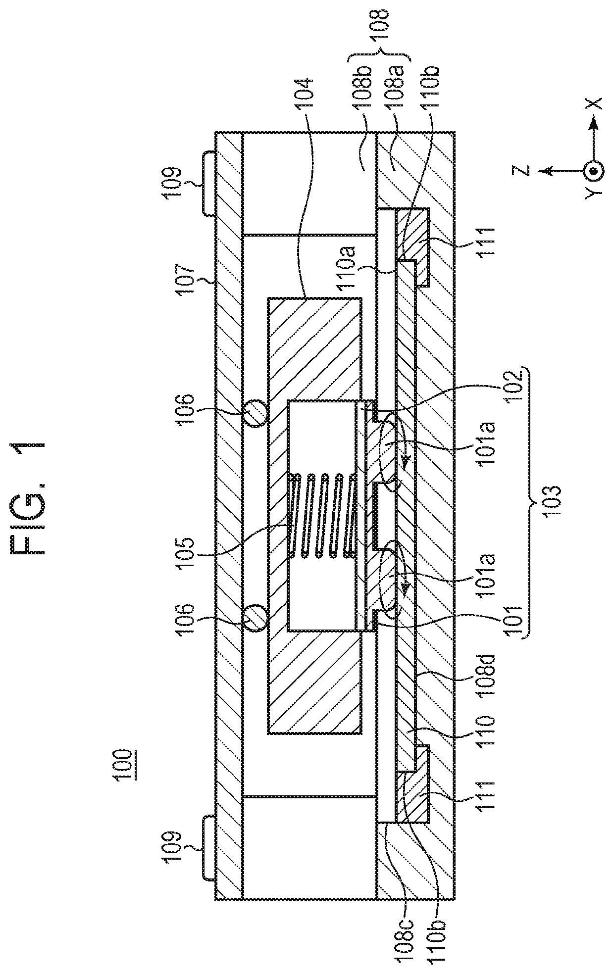
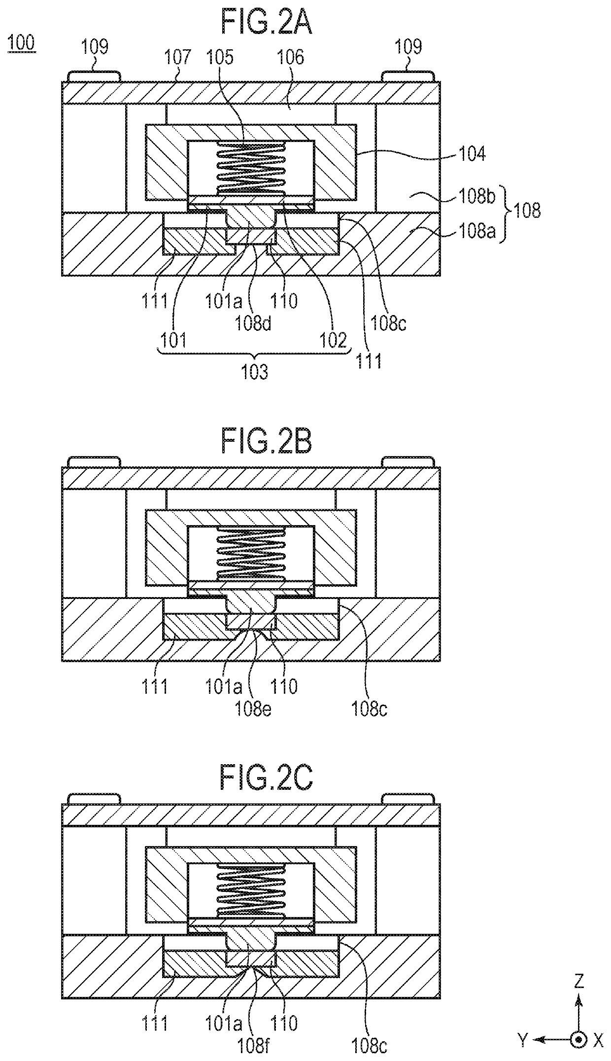
[0015]FIG. 1 is a cross-sectional view illustrating a cross section taken along the X-direction of the vibration wave motor 100 according to an embodiment of the invention. FIG. 2A is a cross-sectional view illustrating a cross section taken along the Y-direction of the vibration wave motor 100. The vibration wave motor 100 according to this embodiment has a long axis in the drive direction and consists of each member described below.

[0016]The vibrator 103 has a vibration plate 101 and a piezoelectric element 102. The piezoelectric element 102 is fixed to the vibration plate 101 using an adhesive known in the art or the like. A method of bonding the vibration plate 101 and the piezoelectric element 102 is not particularly limited as long as they are bonded. The vibration plate 101 further has a frictional contact portion 101a, which comes into contact with the frictional member 110 in a pressurized contact state.

[0017]Vibration of an ultrasonic frequency range (ultrasonic vibration)...


PUM


Abstract

Disclosed is a vibration wave motor including: a vibrator provided with a piezoelectric element and a vibration plate; a frictional member having a frictional contact surface coming into contact with the vibrator; a fixing member having a recess to which the frictional member is fixed; and pressurizing unit that pressurizes the vibrator toward the frictional member, wherein the vibrator and the frictional member make relative movement using vibration generated from the vibrator, a fixing material for fixing the frictional member is provided between the frictional member and the fixing member, and the frictional member is fixed by coming into contact with the fixing member.

Description

BACKGROUND OF THE INVENTIONField of the Invention[0001]The present invention relates to a vibration wave motor, and more particularly, to miniaturization of a linear translation type vibration wave motor.Description of the Related Art[0002]A linear translation type ultrasonic motor has excellent driving efficiency and high driving output power, and can be miniaturized while maintaining high driving output power. For example, a linear translation type ultrasonic motor disclosed in Japanese Patent Application Laid-Open No. 2015-65809 includes a movable portion having a vibrator provided with a piezoelectric element and a pressurizing portion that allows the vibrator to come into pressurized contact with the frictional member, and a fixing member that fixes the frictional member, and three rolling portions and guide portions extending in a movable direction of the movable portion.SUMMARY OF THE INVENTION[0003]However, in the linear translation type ultrasonic motor disclosed in Japanes...

Claims


Application Information

Patent Timeline
Patent Type & Authority Patents(United States)
IPC IPC(8): H02N2/04H02N2/02G02B7/04G03B13/34B06B1/06H02N2/00G02B7/08G03B3/10
CPCH02N2/046B06B1/0644G02B7/04G02B7/08G03B13/34H02N2/001H02N2/006H02N2/0065H02N2/026G03B3/10G03B2205/0061
Inventor TAKAI, KENTA
Owner CANON KK
Why Eureka
Try Eureka