Control device of dynamometer system

a technology of dynamometer and control device, which is applied in the direction of vehicle testing, structural/machine measurement, instruments, etc., can solve the problems of generating a speed difference between the speed of the front wheel roller and the speed of the rear wheel roller, and achieve the effect of preventing the occurrence of oscillatory behavior and quickly eliminating the speed differen

Active Publication Date: 2021-03-09
MEIDENSHA ELECTRIC MFG CO LTD
View PDF11 Cites 1 Cited by
  • Summary
  • Abstract
  • Description
  • Claims
  • Application Information

AI Technical Summary

Benefits of technology

[0019](1) The driving force estimator estimates the generated driving force of the vehicle, and the torque command signal generator uses the generated driving force which is estimated so as to generate the first and second torque command signals for the first and second dynamometers. The synchronization correction signal generator generates the first and second torque correction signals so as to eliminate the speed difference between the first speed and the second speed, and the first and second torque command correctors use the first and second torque correction signals so as to correct the first and second torque command signals. In this way, in the control device of the present invention, while an appropriate load corresponding to the generated driving force of the vehicle is being provided to the vehicle on which the first and second driven members are placed, the first wheel and the second wheel of the vehicle can be synchronized such that the speeds thereof are made equal to each other. In the control device of the present invention, the synchronization correction signal generator is set such that all the poles of the denominator polynomial in the transfer function from the generated driving force to the speed difference are negative real numbers, that is, that all the poles are not oscillatory. In the control device of the present invention, the synchronization correction signal generator set as described above is used so as to generate the first and second torque correction signals, and thus it is possible to prevent the occurrence of an oscillatory behavior in the speed difference between the first speed and the second speed as a control response to the generated driving force that is generated in the vehicle on which the first and second driven members are placed.
[0020](2) In the control device of the present invention, the speed difference is input to the transfer function Gd(s) specified by formula (1) above using the two synchronization control gains Kp and Ti so as to generate the first torque correction signal and the second torque correction signal, and these two synchronization control gains Kp and Ti are set such that all the poles of the denominator polynomial in the transfer function from the generated driving force to the speed difference are negative real numbers. In this way, it is possible to rapidly eliminate the speed difference while an oscillatory behavior is being prevented from occurring in the speed difference between the first speed and the second speed for the generated driving force which is input from the vehicle to the first and second driven members.
[0021](3) In the control device of the present invention, the two synchronization control gains Kp and Ti are set with the inertia Mf and the inertia Mr which can be previously measured and the control response frequency ωc which can be arbitrarily set by formulas (2-1) and (2-2) above. These formulas (2-1) and (2-2) are one of such solutions that all the poles of the denominator polynomial described above are negative real numbers. Hence, in the control device of the present invention, it is possible to eliminate the speed difference between the first speed and the second speed with the response speed corresponding to the control response frequency ωc which can be arbitrarily set while an oscillatory behavior is being prevented from occurring in the speed difference.

Problems solved by technology

However, in the chassis dynamometer system for a four-wheel drive vehicle as described above, the front wheel roller and the rear wheel roller are independently driven without being mechanically coupled to each other, and thus a difference may be produced between the speed of the front wheel roller and the speed of the rear wheel roller.

Method used


Image

  • Control device of dynamometer system
  • Control device of dynamometer system
  • Control device of dynamometer system

Examples


Embodiment Construction

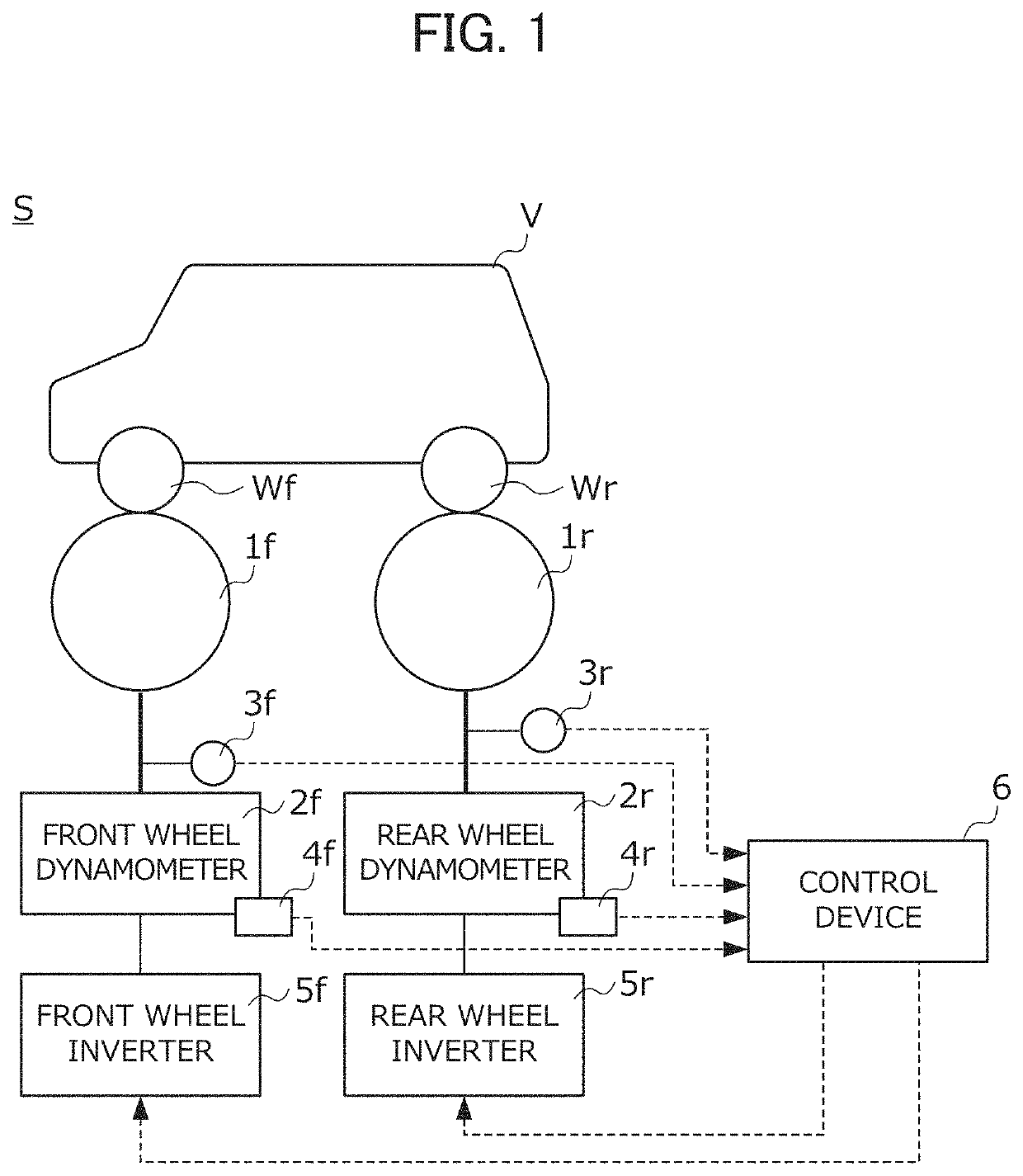
[0026]An embodiment of the present invention will be described below with reference to drawings. FIG. 1 is a diagram showing the configurations of a chassis dynamometer system S and a control device 6 thereof according to the present embodiment. Although the test target vehicle V of the chassis dynamometer system S is a four-wheel drive (4 WD) vehicle which separates and transmits the power thereof to a front wheel Wf and a rear wheel Wr, the present invention is not limited to the four-wheel drive vehicle. The test target vehicle V may be a front-wheel drive (FWD) vehicle or a rear-wheel drive (RWD) vehicle.

[0027]The chassis dynamometer system S includes: a front wheel roller 1f and a rear wheel roller 1r on which the front wheel Wf and the rear wheel Wr of the vehicle V are respectively placed and which are rotated according to the rotations thereof; a front wheel dynamometer 2f and a rear wheel dynamometer 2r which are coupled to these rollers 1f and 1r respectively and coaxially...


PUM


Abstract

A control device of a dynamometer system is provided with: a driving force observer which estimates a generated driving force of a vehicle; an electrical inertia control unit which uses the driving force to generate a front wheel basic torque command signal and a rear wheel basic torque command signal; a synchronization control unit which generates a synchronization control torque command signal with respect to the basic torque command signal and the basic torque command signal in such a way as to eliminate a speed difference; and torque command signal generating units which use the synchronization control torque command signal to adjust the basic torque command signal and the basic torque command signal. The synchronization control unit is defined in such a way that the poles of a denominator polynomial of a transfer function from the driving force to the speed difference are all negative real numbers.

Description

TECHNICAL FIELD[0001]The present invention relates to a control device of a dynamometer system. More specifically, the present invention relates to a control device of a chassis dynamometer system that includes a front wheel roller and a rear wheel roller on which the front wheel and the rear wheel of a vehicle are placed respectively and separately.BACKGROUND ART[0002]In a vehicle test such as a durability test, an exhaust purification performance evaluation test or a fuel consumption measurement test, a chassis dynamometer system is used. The chassis dynamometer system includes a roller on which a wheel of a vehicle serving as a test target is placed and a dynamometer which is coupled to this roller, and traveling resistance such as rolling resistance or inertial resistance produced at the time of actual traveling is provided to the vehicle travelling on the roller by use of the dynamometer and the roller, with the result that conditions close to actual traveling conditions are re...

Claims


Application Information

Patent Timeline
Patent Type & Authority Patents(United States)
IPC IPC(8): G01M17/00G01M17/007
CPCG01M17/0072G01M17/007G01M17/013G01M17/03G01M17/045G01P11/02
Inventor AKIYAMA, TAKAOKIMURA, TOMOAKI
Owner MEIDENSHA ELECTRIC MFG CO LTD
Why Eureka
Try Eureka