Cover for LED luminaires

a technology for led luminaires and covers, which is applied in the direction of light sources, lighting device details, lighting and heating apparatus, etc., can solve the problems of non-uniformity in the luminous distribution over the cross-section of luminaires, and the occurrence of aluminaires that no longer exhibit the desired optical performance, so as to facilitate the design of a light-transmissive cover and improve the overall optical performan

Active Publication Date: 2021-03-16
SIGNIFY HLDG BV
View PDF23 Cites 0 Cited by
  • Summary
  • Abstract
  • Description
  • Claims
  • Application Information

AI Technical Summary

Benefits of technology

[0017]The present inventors have realized that a deterioration in the optical performance of a luminaire comprising rounded corner sections upon replacement of its original light source with SSL equivalents is caused by the reduction in form factor associated with such replacement. In particular, whereas the rounded corner section may be considered small relative to the overall size of the original light source, e.g. a (tubular) light bulb or the like, this consideration no longer holds when replacing the original light source with SSL elements, e.g. LEDs, which may be approximated as point light sources. This causes boundary artefacts at the boundary between the rounded corner section and the further sections, e.g. (near-)planar sections, due to light rays entering the cover through an inner surface of a further section close to a neighbouring rounded corner section exiting an outer surface of the neighbouring rounded corner section, which causes increased divergence of light rays exiting the cover. Such divergence may be reduced by ensuring that the cover is designed such that substantially all light rays entering a further section of the cover also exit from the further section. This reduction is ensured by positioning the inner and outer endpoints of such a curved corner section as recited above. Said divergence can even be further reduced when at the endpoints a tangent to the surface of the rounded corner section is parallel to a tangent to a proximal further inner surface of its proximal further section, i.e. both the inner and outer surface have a smooth transision between the further, linear, planar section and the rounded corner section, in other words said transition is without a discontinuity, such as a kink or step.
[0030]According to still a further aspect, there is provided a method of manufacturing a light-transmissive cover for a luminaire housing, the cover having a defined refractive index and comprising at least one rounded corner section in between two further sections, the method comprising manufacturing a mold for the light-transmissive cover using the design specification, including generating an output of a design specification of the light-transmissive cover including wall-thickness Tw, and relative positions of inner end points and proximal outer end points and the defined first and second splines as produced by the aforementioned computer-implemented method and manufacturing the light-transmissive cover with said mold to provide a light-transmissive cover with improved optical performance as explained above.

Problems solved by technology

Consequently, the luminaire may no longer exhibit the desired optical performance due to the fact that SSL elements have a distinctly different optical characteristic compared to previous generation light sources such as (tubular) incandescent or fluorescent lighting.
Such optical artefacts include non-uniformity in the luminous distribution over the cross-section of the luminaire both in terms of colour and intensity, e.g. dark and bright lines as well as colour effects that become visible on the surfaces onto which the luminous distribution of such a luminaire is projected.

Method used


Image

  • Cover for LED luminaires
  • Cover for LED luminaires
  • Cover for LED luminaires

Examples


Embodiment Construction

[0044]It should be understood that the Figures are merely schematic and are not drawn to scale. It should also be understood that the same reference numerals are used throughout the Figures to indicate the same or similar parts.

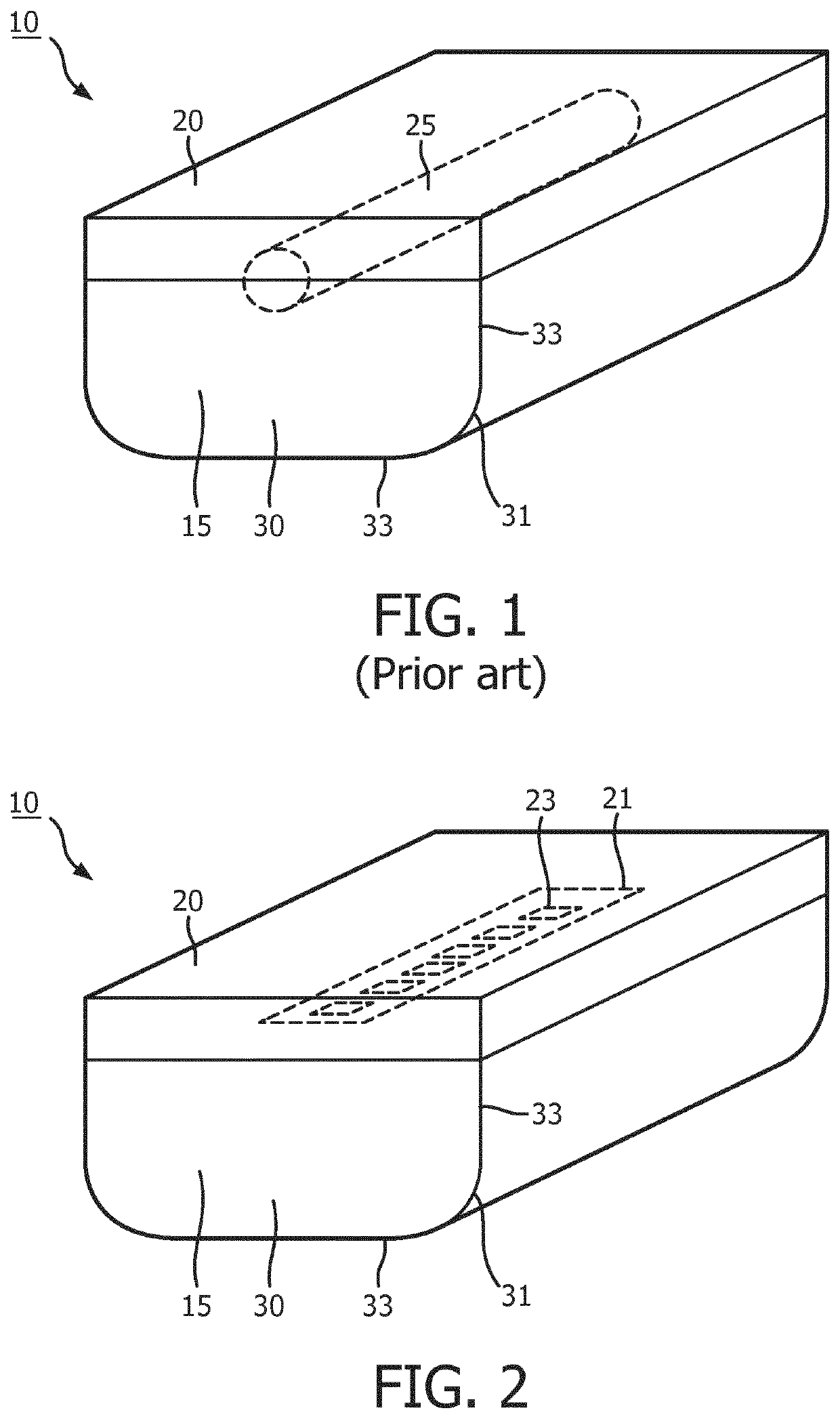
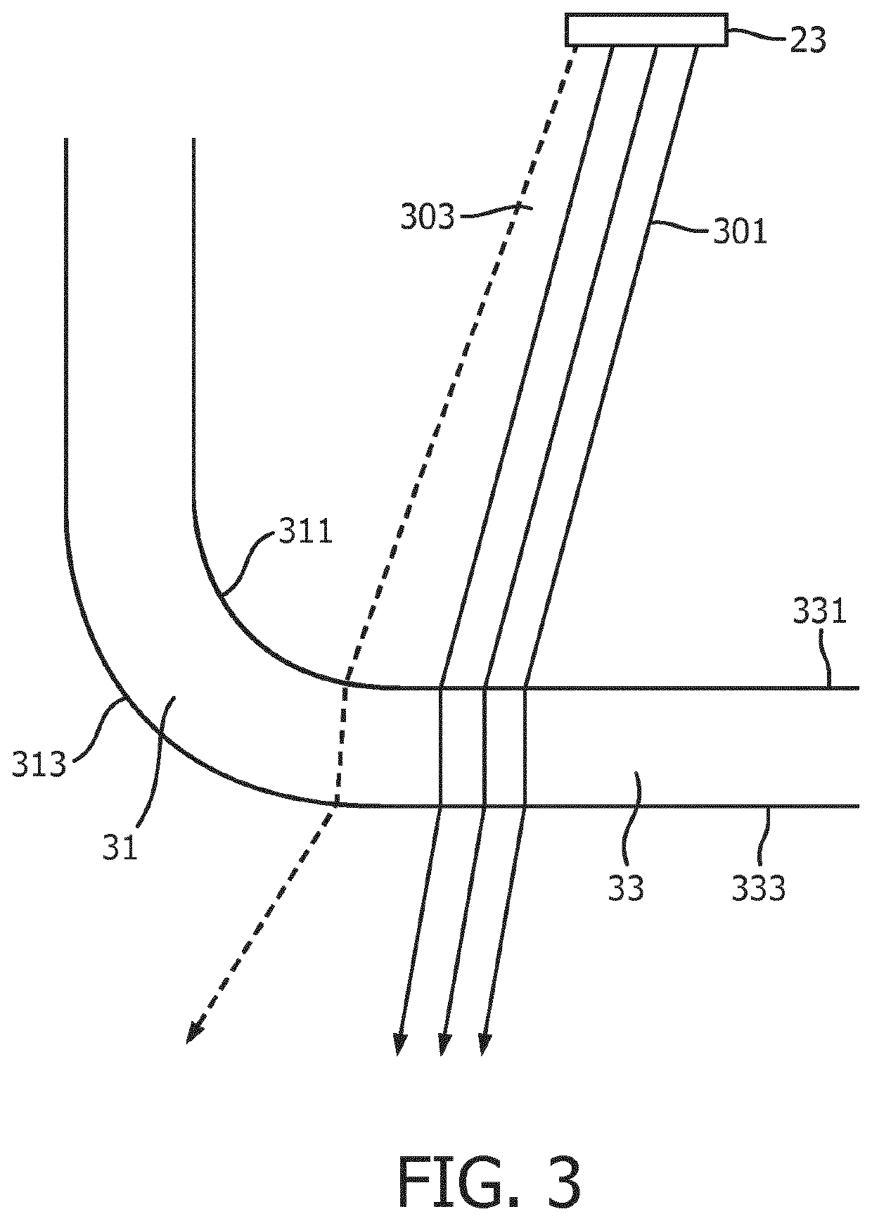
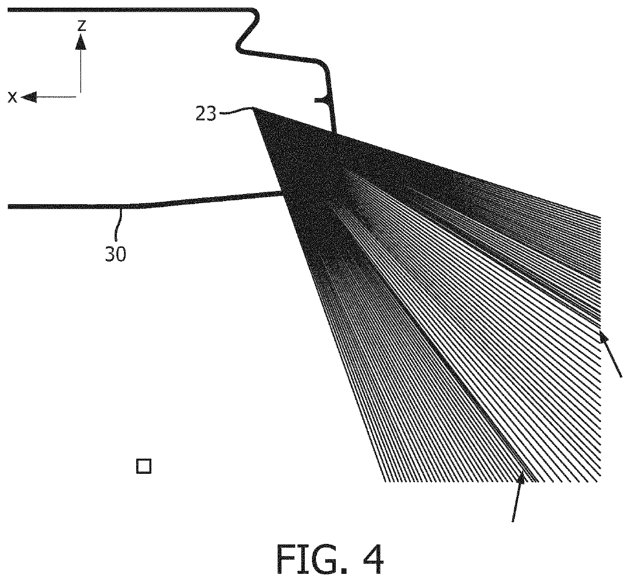
[0045]FIG. 3 schematically depicts an aspect of a prior art light-transmissive cover 30 as depicted in FIG. 1 when equipped with SSL elements 23 as schematically depicted in FIG. 2. FIG. 3 highlights a root cause of the optical artefacts that may occur in such a scenario. The light-transmissive cover 30 is typically designed using CAD software in which one of the inner surface 311 and the outer surface 313 of the curved corner section 31 is drawn after which an offset function in the CAD software is used to generate the other of the inner surface 311 and the outer surface 313, thereby generating opposing curved surfaces with a different radial distance (corresponding to a constant wall thickness of the cover 31) from a central point used to define these curve...


PUM

PropertyMeasurementUnit
angleaaaaaaaaaa
angle of incidence θiaaaaaaaaaa
angleaaaaaaaaaa

Abstract

A luminaire housing (10) comprises a light chamber (15) at least partially delimited by a light-transmissive cover (30). The light chamber comprises a mounting region for mounting at least one solid state lighting element. The cover comprises at least one rounded corner section (31) in between two further sections (33), wherein the rounded corner section has an inner surface (311) having opposing inner endpoints (103, 105) and an outer surface (313) having opposing outer endpoints (113, 115). Each inner endpoint is positioned relative to the outer endpoint proximal to said inner endpoint such that no ray of light (301, 301′) emitted by the at least one solid state lighting element entering the light-transmissive cover via an inner surface (331) of a further section exits the light-transmissive cover from the outer surface of a curved corner section. A luminaire including such a luminaire housing, a design method and a manufacturing method for such a luminaire housing are also disclosed.

Description

CROSS-REFERENCE TO PRIOR APPLICATIONS[0001]This application is the U.S. National Phase application under 35 U.S.C. § 371 of International Application No. PCT / EP2017 / 079471, filed on Nov. 16, 2017 which claims the benefit of European Patent Application No. 16200018.6, filed on Nov. 22, 2016. These applications are hereby incorporated by reference herein.FIELD OF THE INVENTION[0002]The present invention relates to a luminaire housing comprising a light chamber delimited by a light-transmissive cover comprising at least one rounded corner section in between two further sections.[0003]The present invention further relates to a luminaire comprising such a luminaire housing.[0004]The present invention further relates to a method of designing such a luminaire housing.[0005]The present invention further relates to a method of manufacturing such a luminaire housing.BACKGROUND OF THE INVENTION[0006]Solid state lighting (SSL), e.g. LED lighting, is becoming increasingly popular due to its much...

Claims


Application Information

Patent Timeline
Patent Type & Authority Patents(United States)
IPC IPC(8): F21V3/02F21K9/27F21Y103/10F21Y115/10
CPCF21V3/02F21K9/27F21Y2103/10F21Y2115/10
Inventor THIJSSEN, JOHANNES MARIABOOIJ, SILVA MARIA
Owner SIGNIFY HLDG BV
Why Eureka
Try Eureka