Lighting apparatus

Active Publication Date: 2013-05-23
KONINKLIJKE PHILIPS ELECTRONICS NV
View PDF3 Cites 9 Cited by
  • Summary
  • Abstract
  • Description
  • Claims
  • Application Information

AI Technical Summary

Benefits of technology

[0004]It is an object of the present invention to provide a lighting apparatus and a lighting me

Problems solved by technology

This reduces the maximally obtainable intensity of the laser beam on the retina and, thus, the

Method used


Image

  • Lighting apparatus
  • Lighting apparatus
  • Lighting apparatus

Examples


Embodiment Construction

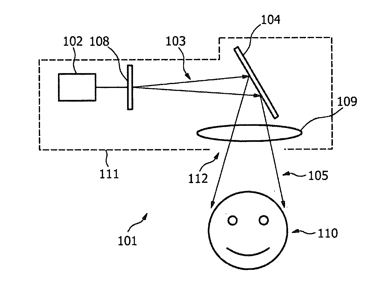
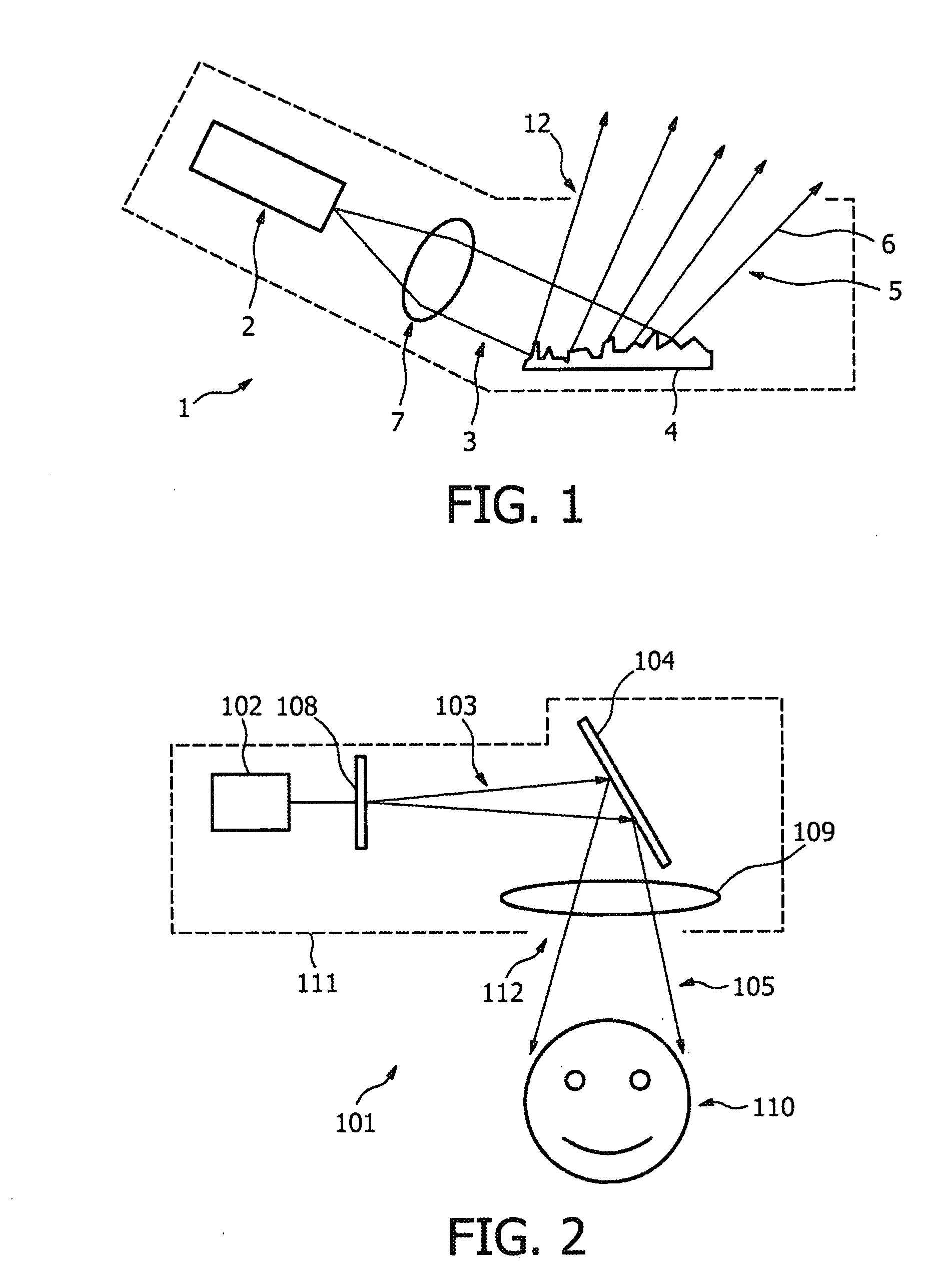
[0028]FIG. 1 shows schematically and exemplarily an embodiment of a lighting apparatus 1 comprising a laser 2 for emitting a first laser beam 3. The lighting apparatus 1 further comprises a diffractive reflective element 4 being, in this embodiment, a holographic reflective element. The first laser beam 3 is collimated by a lens 7 for parallelizing the first laser beam 3, wherein by using the divergence of the first laser beam 3 the first laser beam 3 is expanded before being collimated by the lens 7. The first laser beam 3 and the holographic reflective element 4 are arranged such that the first laser beam 3 is reflected by the holographic reflective element 4 for generating a second laser beam 5. The second laser beam 5 comprises several reflected rays 6 which point at least partly in different directions. The holographic reflective element 4 is adapted such that the effective surface area of the second laser beam 5 is larger than the effective surface area of the first laser beam...


PUM


Abstract

The invention relates to a lighting apparatus comprising a laser (102) for emitting a first laser beam (103) and a diffractive reflective element (104). The first laser beam (103) is reflected by the diffractive reflective element (104) for generating a second laser beam (105) being the reflected first laser beam, wherein the diffractive reflective element (104) is adapted such that the effective surface area of the second laser beam (105) is larger than the effective surface area of the first laser beam (103). The second laser beam is supposed to be pointed directly or indirectly to the eyes of a person. Since the diffractive reflective element increases the effective surface area and is used in a reflective mode, i.e. the first laser beam will generally not directly meet the eye of the person, if the diffractive reflective element is damaged or displaced, the risk of eye damages can be reduced.

Description

FIELD OF THE INVENTION[0001]The invention relates to a lighting apparatus and a lighting method.BACKGROUND OF THE INVENTION[0002]US 2007 / 0109784 A1 discloses a lighting apparatus comprising a laser emitting a laser beam being expanded by a negative lens and collimated by a positive lens. The expanded collimated light beam is directed onto a transmissive holographic diffuser to produce a diffused light beam. The diffused light beam has an expanded cross section and provides an extended glare source at increased power downrange. The extended source produced by the holographic diffuser creates an extended image on the retina of the human eye. The extended retinal image permits a higher power laser exposure, compared to a point source image common in conventional designs.[0003]This lighting apparatus has the drawback that, if the holographic diffuser of the lighting apparatus is damaged, the dimensions of the image on the retina can be varied, in particular, reduced. This could lead to ...

Claims


Application Information

Patent Timeline
IPC IPC(8): G02B27/09G02B5/02
CPCG02B5/0221G02B5/0252G02B27/0977G02B5/32G02B5/02G02B5/0284F21S41/16
Inventor HIKMET, RIFAT ATA MUSTAFA
Owner KONINKLIJKE PHILIPS ELECTRONICS NV
Why Eureka
Try Eureka