User interface for automated flows within a cloud based developmental platform

Active Publication Date: 2021-03-23
SERVICENOW INC
View PDF76 Cites 3 Cited by
  • Summary
  • Abstract
  • Description
  • Claims
  • Application Information

AI Technical Summary

Benefits of technology

[0007]In one embodiment, an automation system to create and manage flow plans within a cloud computing environment. To create and manage flow plans, a developmental platform includes an automation system that minimizes the use of customized scripting and coding. The automation user interface system comprises a flow designer user interface that allows a user to arrange one or more action and trigger instances in a sequence to form a design-time flow plan, an action designer user interface that configures action instances by creating one or more step instances, and a construction API that builds a data model within a database. The flow designer user interface, the action designer user interface, and the construction API drive the data model so that the design-time flow plan can be continuously updated and / or saved independent of any run-time operations.
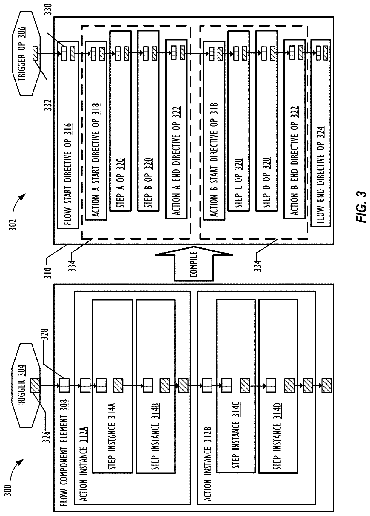
[0013]In another embodiment, a method that that creates a trigger for a design-time flow plan that activates when one or more computing conditions are met. The method defines multiple action instances for the design-time flow plan that execute after the trigger activates. The one or more of the action instances comprise a respective sequence of step instances associated with respective inputs and outputs. The method saves the design-time flow plan within a data model and convert the saved design-time flow plan into a run-time flow plan. The method calls a flow engine to execute the operations within the run-time flow plan such that the execution of the one or more operations within run-time flow plan occurs as the data model saves an updated design-time flow plan. The operations within the run-time flow plan also include at least one dynamic mutable operation.
[0016]In yet another embodiment, an automation backend system separate from a flow engine. The automation backend system creates a trigger for a design-time flow plan that activates when one or more computing conditions are met and defines a plurality of action instances for the design-time flow plan that would execute after the trigger activates. Each of the plurality of action instance includes a respective sequence of step instances associated with respective inputs and outputs. The automation backend system is able to save the design-time flow plan within a data model that includes an action type table that is linked to an action instance table, but not to a flow plan table.

Problems solved by technology

Requiring customized script to build automated processes may pose a challenge when attempting to address abstraction (e.g., providing domain-appropriate building blocks), code reuse (e.g., having defined application program interface (API) semantics), and / or codeless development.

Method used


Image

  • User interface for automated flows within a cloud based developmental platform
  • User interface for automated flows within a cloud based developmental platform
  • User interface for automated flows within a cloud based developmental platform

Examples


Embodiment Construction

[0050]In the following description, for purposes of explanation, numerous specific details are set forth in order to provide a thorough understanding of the embodiments disclosed herein. It will be apparent, however, to one skilled in the art that the disclosed embodiments may be practiced without these specific details. In other instances, structure and devices are shown in block diagram form in order to avoid obscuring the disclosed embodiments. References to numbers without subscripts or suffixes are understood to reference all instance of subscripts and suffixes corresponding to the referenced number. Moreover, the language used in this disclosure has been principally selected for readability and instructional purposes, and may not have been selected to delineate or circumscribe the inventive subject matter, resort to the claims being necessary to determine such inventive subject matter. Reference in the specification to “one embodiment” or to “an embodiment” means that a partic...


PUM


Abstract

Creating, executing, and managing flow plans by performing at least the following: presenting on a display an action instance associated with a flow plan within an action designer user interface, wherein the action designer user interface comprises: an action outline component that includes an input graphical element, one or more step instance graphical element, and an action graphical element, wherein one of the graphical elements is highlighted within the action outline component; and an action window adjacent to the action outline component, wherein the action window comprises one or more input fields that dynamically change based on a user selection of one of the graphical elements within the action outline component, and present a window to select from a list of pre-existing step instance types for a step instance.

Description

CROSS-REFERENCE TO RELATED APPLICATIONS[0001]This application claims the benefit of U.S. Provisional Patent Application No. 62 / 557,427, filed Sep. 12, 2017 by Harry Thomas Nelson et al. and entitled “Automated Flows within a Cloud Based Developmental Platform,” and U.S. Provisional Patent Application No. 62 / 502,258, filed May 5, 2017 by Sarup Paul et al. and entitled “Service Platform and Use Thereof,” and is related to U.S. Design patent application Ser. No. 29 / 617,193 filed Sep. 12, 2017 by Qian Zhang et al. and entitled “Graphical User Interface for a Display Screen of a Communications Terminal,” all of which are hereby incorporated by reference as if reproduced in their entirety.TECHNICAL FIELD[0002]Embodiments described herein generally relate to cloud computing and in particular to creating, executing, and managing flow plans within a cloud based developmental platform.BACKGROUND ART[0003]Cloud computing involves sharing of computing resources that are generally accessed via t...

Claims


Application Information

Patent Timeline
Patent Type & Authority Patents(United States)
IPC IPC(8): G06F3/048G06F3/0484G06F9/54G06F3/0482H04L12/24H04L29/08G06F16/27G06Q10/06
CPCG06F3/04847G06F3/0482G06F9/54G06F16/27G06Q10/0631H04L41/22H04L67/1097G06F9/5038
Inventor NELSON, HARRY THOMASDIAS, REBECCABRENNAN, MARKZHANG, QIANMITCHELL, CHRISTEN
Owner SERVICENOW INC
Why Eureka
Try Eureka