Lens module

a technology of lens module and lens body, applied in the field of lens module, can solve the problems of reducing the quality of images, reducing the ability of image capture module, and weak structural strength, so as to improve the ability of impact, increase the structural strength, and endure the effect of friction

Active Publication Date: 2021-03-30
TDK TAIWAN
View PDF12 Cites 0 Cited by
  • Summary
  • Abstract
  • Description
  • Claims
  • Application Information

AI Technical Summary

Benefits of technology

[0004]The primary objective of the present invention is to provide a lens module; in which, all or part of a metal embedded member is embedded in a rim portion with relatively thinner thickness of a lens unit or a frame in order to increase the structural strength, endure ability of impact and endure ability of friction at the rim portion of the lens unit or the frame.
[0005]Another objective of the present invention is to provide a lens module, wherein the embedded member comprises a plurality of protrusions which is exposed outside of the rim portion or the frame. When the lens unit moves relative to the frame, the positions where the lens unit might touch the frame are the locations of the protrusions. Therefore, these metal made protrusions can act as the impact positions between the lens unit and the frame to avoid contacts between plastic components, so as to prevent the lens unit and frame from deformations or damages due to impacts.
[0006]A further objective of the present invention is to provide a lens module, wherein the driving coils can be electrically connected with the protrusions of the embedded member, such that the electricity required by the coils can be transmitted via the embedded member, so as to improve the flexibility of circuitry design.

Problems solved by technology

Especially, at the outer rims of both the lens set and the frame, the structural strengths are even weaker and inadequate since the thicknesses thereof are relatively thinner.
However, during the operations when the lens set is driven to perform Auto-Focusing (AF) function or the frame is driven to perform OIS function, impacts occur from time to time between the lens set and the frame, or between the frame and the casing, and moreover, such impacts are mostly happened right at the outer rims of the lens set and the frame where are weakest in strength.
Therefore, after a period of time of operations, it is very easy to find some deformations, ruptures or wear at the outer rims of the lens set and the frame caused by impacts and frictions, and thus results in defects such like decreased quality of images or malfunction of image capture module.

Method used


Image

  • Lens module
  • Lens module
  • Lens module

Examples


first embodiment

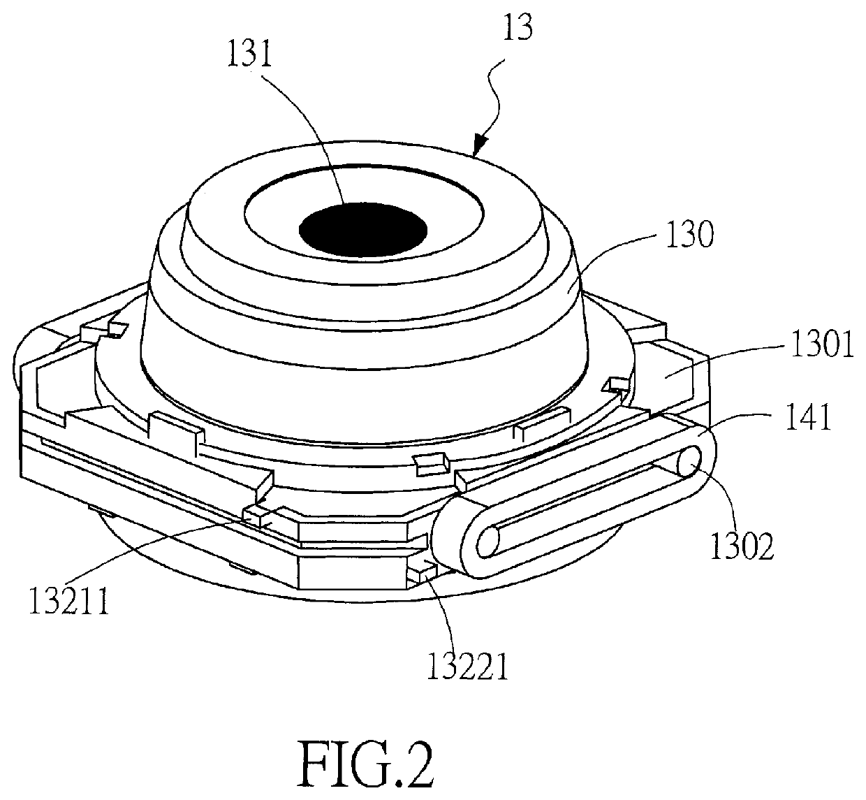
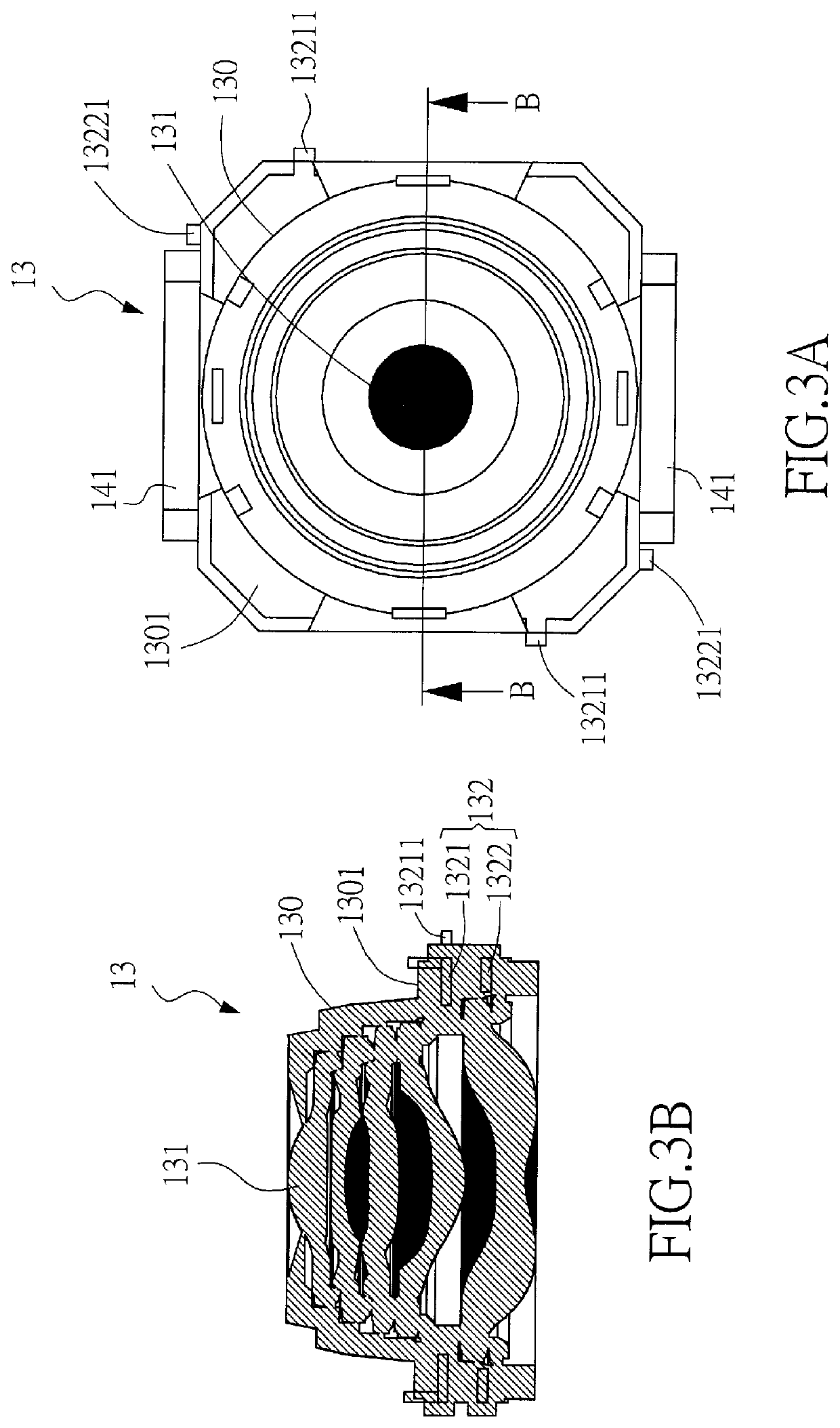
[0075]As shown in FIG. 2, in the present invention, the lens unit 13 further comprises: a body 130, at least one lens 131, and at least one embedded member 132 (see also FIG. 4). The body 130 is made of a first material. The body 130 has a rim portion 1301, a central through hole, and a plurality of positioning elements 1302. The positioning elements 1302 can be wound or fitted by the coil 141 to achieve the function of fixing the coil 141 to the positioning elements 1302. In this embodiment, the coil 141 can be a flat coil to reduce space and increase strength. The at least one lens 131 is located at the central through hole of the body 130. An optical axis can be defined by the at least one lens 131 for an external image light to pass through the lens unit 13 along the optical axis. The at least one embedded member 132 is made of a second material, and the hardness of the second material is greater than the hardness of the first material. The lens unit 13 is integrally formed by e...

third embodiment

[0083]Please refer to FIG. 8, which is a perspective view of the lens unit placed on the bottom plate of the present invention as shown in FIG. 6. In this embodiment, the plastic bottom plate 19 can also be embedded with a metal embedded member (not shown in this figure) by using the plastic insert-molding process or other processes. In addition, a plurality of protrusions 193 projected upwardly are also provided on the embedded member such that the protrusions 193 can protrude upward and be exposed to the upper surface of the bottom plate 19. When the lens unit 13 is driven by the first driving module to move relative to the bottom plate 19 along the optical axis, the bottom plate 19 provides a stopping function for the lower end of the lens unit 13 to limit the moving range of the lens unit 13. The positions of the upwardly projected protrusions 193 exposed on the upper surface of the bottom plate 19 respectively correspond to the positions of the additional protrusions 13222 prot...


PUM


Abstract

A lens module comprises a frame, a lens unit, and a driving module for driving the lens unit to move relative to the frame. The lens unit comprises a body made of plastic, at least one lens located in a center of the body, and an embedded member made of metal. The metal embedded member is embedded within a thinner rim portion of the lens unit by means of a plastic insert-molding process in such a manner that, at least one protrusion of the metal embedded member is exposed outside of the rim portion. When the lens unit moves relative to the frame, a location where the lens unit might touch the frame is one of the at least one protrusion, and therefore the structural strength, endure ability of impact and endure ability of friction at the rim portion of the lens unit are increased. In addition, the protrusion can also act as a positioning post or winding post for a coil of the driving module. Or, the coil can also be electrically connected to the protrusion such that the metal embedded member can transmit electric current for the coil.

Description

RELATED CASES[0001]This application claims the benefit of U.S. provisional patent application Ser. No. 62 / 553,236, filed on Sep. 1, 2017, whose disclosures are incorporated by this reference as though fully set forth herein.BACKGROUND OF INVENTION1. Field of the Invention[0002]The invention refers to a lens module, especially refers to a lens module that uses a plastic insert-molding process to embed a metal embedded member within a thinner rim portion of a lens unit so as to increase the structural strength and the endure abilities of impact and friction at the rim portion.2. Description of the Prior Art[0003]Miniaturization is a trend of novel designs for image capturing modules nowadays, especially for the image capturing modules furnished in portable electronic devices such like smart phones, tablet computers or notebook computers, the overall size of which is even as small as (6 mm)3 or less. In order to accommodate the casing, the lens set, the voice coil motor (VCM) including...

Claims


Application Information

Patent Timeline
Patent Type & Authority Patents(United States)
IPC IPC(8): G02B7/09G02B7/02G02B7/08G02B27/64
CPCG02B7/09G02B7/021G02B7/08G02B27/646G02B7/02
Inventor HU, CHAO-CHANGHUANG, SHAO-KUANGWENG, CHIH-WEI
Owner TDK TAIWAN
Why Eureka
Try Eureka