Plate laminate type heat exchanger

a heat exchanger and laminate technology, applied in the direction of manufacturing tools, soldering devices, light and heating equipment, etc., can solve the problems of poor joining between plates, new problems, deterioration of flatness or the like, etc., and achieve the effect of not restrainting the aging process, and reducing the cost of production

Active Publication Date: 2021-04-13
T RAD CO LTD
View PDF10 Cites 2 Cited by
  • Summary
  • Abstract
  • Description
  • Claims
  • Application Information

AI Technical Summary

Benefits of technology

[0020]In a heat exchanger configured in this way, in a brazing process, each of laminated plates is temporarily fixed with a fixing pin and, therefore, displacement between each plate and the like is not generated. Moreover, only one end part of the fixing pin in the longitudinal direction is fixed to the round hole and, therefore, shrinkage by baking is not restrained in brazing. Hereby, it becomes possible to satisfy both temporary fixing of laminated plates and non-restraint of shrinkage by baking with a convenient and inexpensive method. As the result, an excellent heat exchanger, in which a complexity in the structure due to an addition of a complex part, poor joining between plates and deterioration in flatness do not exist, can be provided.
[0024]In a heat exchanger configured in this way, in a brazing process, each of laminated plates is temporarily fixed with a fixing pin and, therefore, displacement between each plate and the like is not generated. Moreover, only one end part of the fixing pin in the longitudinal direction is fixed to a round hole and, therefore, shrinkage by baking is not restrained in brazing. Hereby, it becomes possible to satisfy both temporary fixing of laminated plates and non-restraint of shrinkage by baking, with a convenient and inexpensive method. As the result, an excellent heat exchanger, in which a complexity in the structure due to an addition of a complex part, poor joining between plates and deterioration in flatness do not exist, can be provided.

Problems solved by technology

However, in the case where the restraining system as disclosed in Japanese Patent No. 3026315 is adopted for improving a temporary fixing system in a “loosely fitted” state, a new problem is generated.
That is, in a brazing process, there is generated decrease in dimension in the laminate direction due to melting and liquation of a brazing material, that is, a so-called “shrinkage by baking” phenomenon, and, on this occasion, if a pin for fixing or the like is wholly restrained, the shrinkage by baking is also restrained to cause poor joining between each plate, deterioration in flatness or the like.
In the case where a pin of this type is used, restraint in shrinkage by baking may be relieved, but a molten brazing material intrudes inside the pin from the groove part of the grooved spring pin in brazing, and therefore there are left other problems such that the “shrinkage by baking” phenomenon increases by the amount, the pin itself is an expensive part, and the like.

Method used


Image

  • Plate laminate type heat exchanger
  • Plate laminate type heat exchanger
  • Plate laminate type heat exchanger

Examples


first embodiment

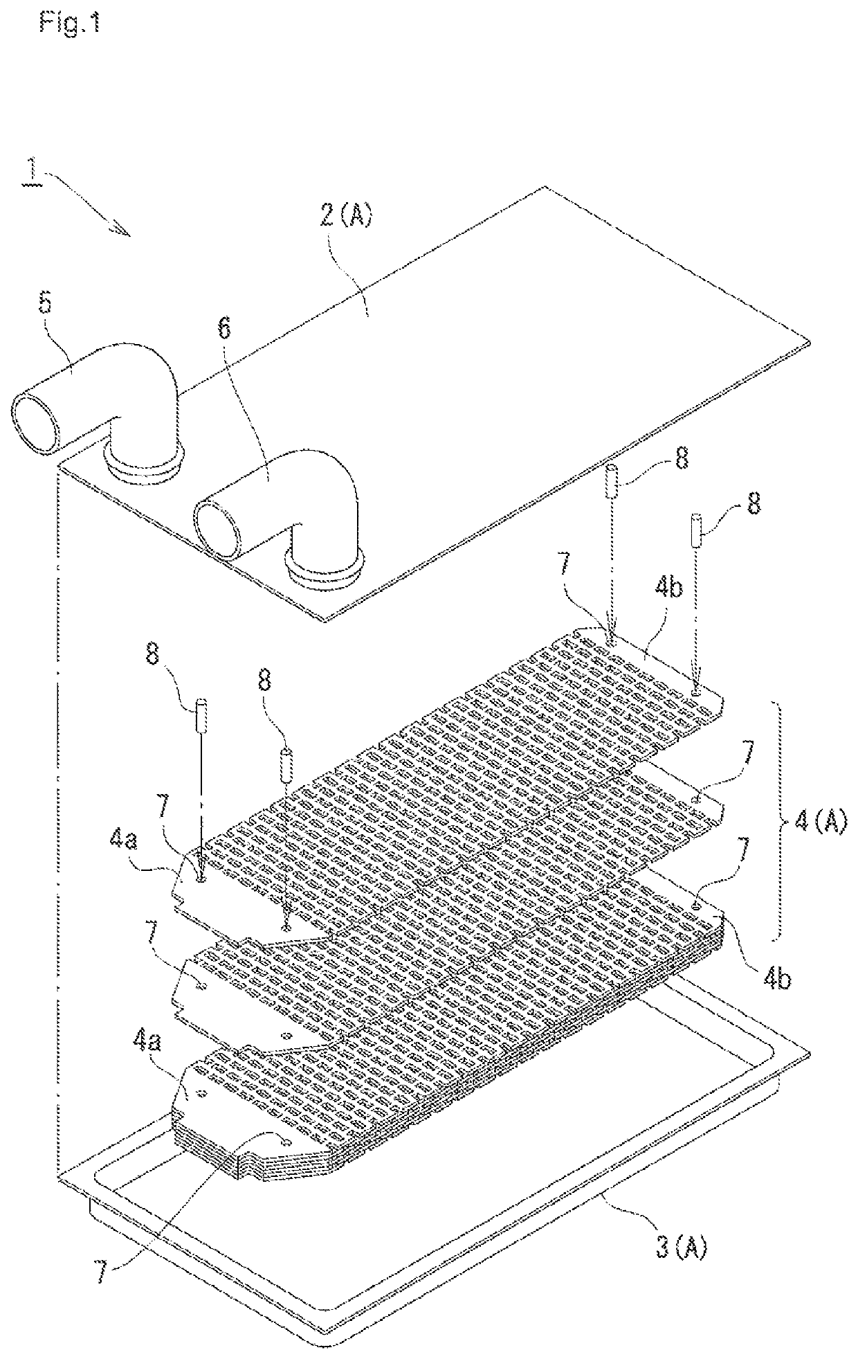
1 illustrates, in a cup plate type heat exchanger in the present invention, an exploded perspective view before brazing of the heat exchanger. A heat exchanger 1 includes a top plate 2 on the upper side, a bottom plate 3 on the lower side, and plural inner plates 4 to be laminated therebetween, and, for the top plate 2, a fluid inlet pipe 5 for supplying a fluid such as cooling water and a fluid outlet pipe 6 for discharging the fluid are provided. The bottom plate 3 has a sidewall part on a peripheral part, and it is configured so that a flange formed on the upper part of the sidewall part and a peripheral part of the top plate 2 can be joined.

[0039]In the present invention, in the case where each of plates such as the top plate 2, the bottom plate 3 and the inner plate 4 is described all together, they are referred to generically as plates A. Note that these plates A are made of metal, and, generally, a plate material of an aluminum alloy or stainless steel is used as the metal ma...

second embodiment

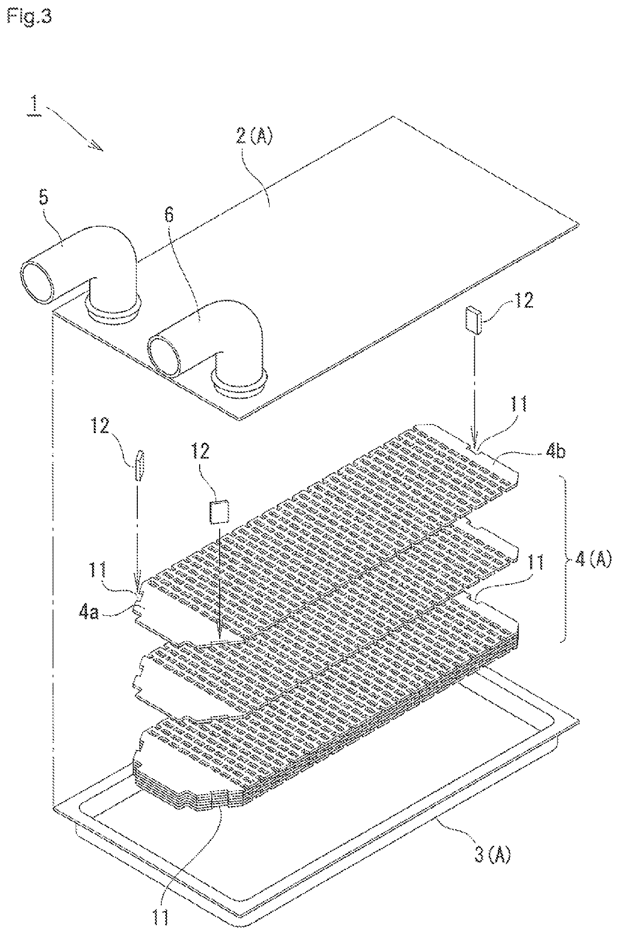
[0047]FIG. 3 illustrates an exploded perspective view showing a state, in a cup plate type heat exchanger in the present invention, before brazing of the heat exchanger. A different portion of the embodiment in FIG. 3 from the embodiment in FIG. 1 is only the fixing system of laminated inner plates, and the others are configured in the same way. Accordingly, the same reference sign is given to the same portion as in FIG. 1 and overlapping explanation will be omitted.

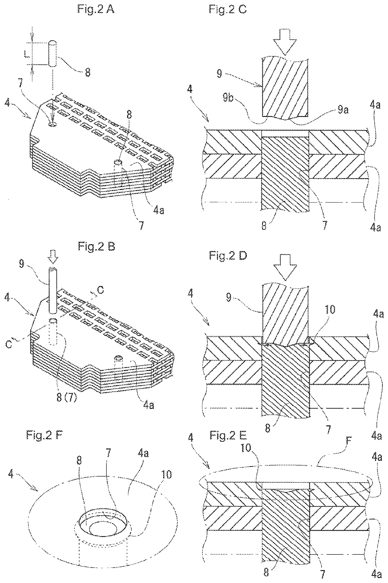
[0048]In the embodiment in FIG. 3, cutout parts 11 each having a square-shaped cross-section in the laminate direction are formed in two positions of the peripheral part at one end part 4a of each inner plate 4 and in one position of the peripheral part at the other end part 4b. Note that it is configured such that, when each inner plate 4 is laminated so as to match with each other, each cutout part 11 also matches coaxially with each other. Then, the fixing plate 12 is inserted into every cutout part 11 in each inner p...

third embodiment

[0054]FIG. 6 illustrates an exploded perspective view before brazing of a complete laminate type heat exchanger in the present invention. Different points of the heat exchanger of the complete laminate type in FIG. 6 from the cup plate type heat exchanger in FIG. 1 are a mutual structural bonding form between the top plate 2, the bottom plate 3 and plural inner plates 4 to be laminated therebetween, the shape of peripheral part of each plate matching with the bonding form, and the like. However, the insertion form and fitting form between each plate and the fixing pin or the like, which are characteristic portions of the present invention, are configured in the same way. Accordingly, to the same portions in FIG. 1 and FIG. 6, the same reference sign as in FIG. 1 is given and an overlapping explanation will be omitted.

[0055]In FIG. 6, each of the top plate 2, the bottom plate 3 and plural inner plates 4 is formed in a square shape, and, at four corners of all the plates A, a bolt hol...


PUM

PropertyMeasurementUnit
outer diameteraaaaaaaaaa
diameteraaaaaaaaaa
total thicknessaaaaaaaaaa

Abstract

To provide a plate laminate type heat exchanger that is capable to be temporarily fixed easily and surely before brazing assembly and can be fabricated with good accuracy. In a plate laminate type heat exchanger using a cladding material cladded with a brazing material, in each of laminated plates, a round hole penetrating in a laminate direction is formed; a thin and long fixing pin is inserted into the round hole so as to communicate each of plates; the fixing pin is fixed to the round hole by expansion of the outer diameter only at one end part in the longitudinal direction of the fixing pin; and each of plates is temporarily fixed integrally.

Description

BACKGROUND OF THE INVENTION[0001]The present invention relates to a plate laminate type heat exchanger applicable to a cooler and the like for cooling electronic devices such as an inverter.[0002]Heretofore, as a plate laminate type heat exchanger applicable to a cooler for electronic devices such as an inverter and the like, there are known a cup plate type structure in which laminated inner plates are encompassed using a top plate or bottom plate in a cup shape, a complete laminate type structure in which plates having a circulation path therein are laminated and the top and bottom thereof are sealed with flat board-like plates, and the like.[0003]With respect to these plate laminate type heat exchangers, generally the whole of a heat exchanger is integrally brazed and manufactured, but, in brazing, mutual plates such as inner plates needs to be laminated and temporarily fixed in a positioned state. As methods of temporary fixing, a method of welding an outer peripheral part of a ...

Claims


Application Information

Patent Timeline
Patent Type & Authority Patents(United States)
IPC IPC(8): F28D9/02B23K1/00B23K3/00H05K7/20F28F21/08F28F3/08F28F3/12F28F3/06F28D21/00
CPCF28D9/02B23K1/00B23K3/00F28F3/06F28F3/08F28F3/086F28F3/12F28F21/089H05K7/20254F28D2021/0029
Inventor BUNGO, TAKUYAOKUBO, ATSUSHISAKAI, TAIJI
Owner T RAD CO LTD
Why Eureka
Try Eureka