Low temperature low hydration heat cementing cement system

A cementing technology with low heat of hydration, applied in low-temperature surface cementing and onshore permafrost fields, to achieve low water loss, prevent dry shrinkage, and prevent thermal decomposition

Inactive Publication Date: 2008-12-24
CHINA UNIV OF PETROLEUM (EAST CHINA)
View PDF1 Cites 29 Cited by
  • Summary
  • Abstract
  • Description
  • Claims
  • Application Information

AI Technical Summary

Problems solved by technology

However, the cementing of deep-water hydrate layers has not been carried out in China. Therefore, it is necessary to research and develop suitable A new low-temperature cementing system with low heat of hydration and early strength in hydrate formations

Method used


Image

  • Low temperature low hydration heat cementing cement system
  • Low temperature low hydration heat cementing cement system
  • Low temperature low hydration heat cementing cement system

Examples


Embodiment 1

[0019] Example 1, performance evaluation of the low heat of hydration cement system of the present invention with low heat of hydration

[0020] Cement components: G-grade oil well cement 41.59%, ultra-fine slag 30%, fly ash 18.10%, gypsum 4.06%, and the rest are other minor admixtures. Code-named sample LHC-1.

[0021] Cement components: G-grade oil well cement 32.40%, ultra-fine slag 32.02%, fly ash 28.42%, gypsum 4.01%, and the rest are other minor admixtures. Codenamed sample LHC-2.

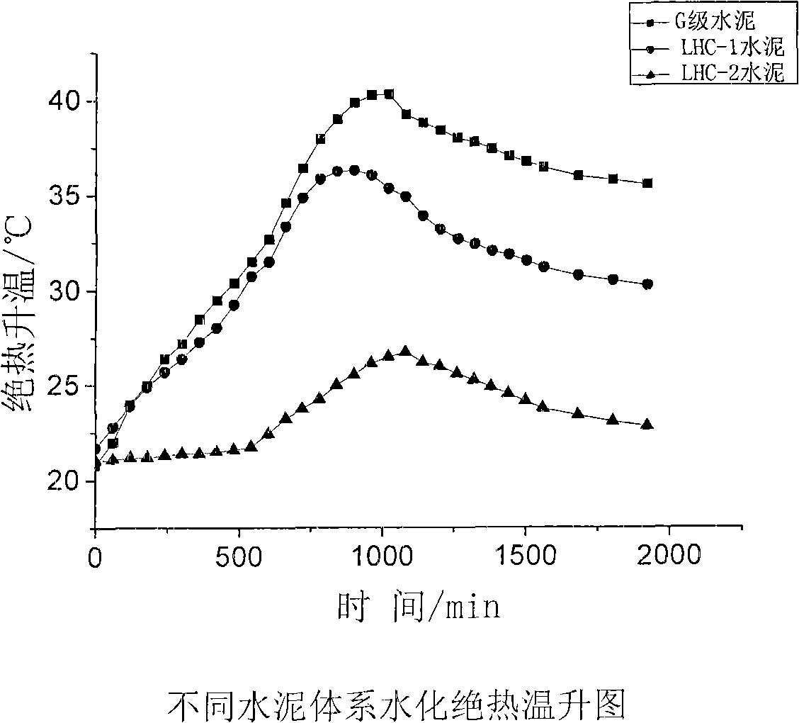
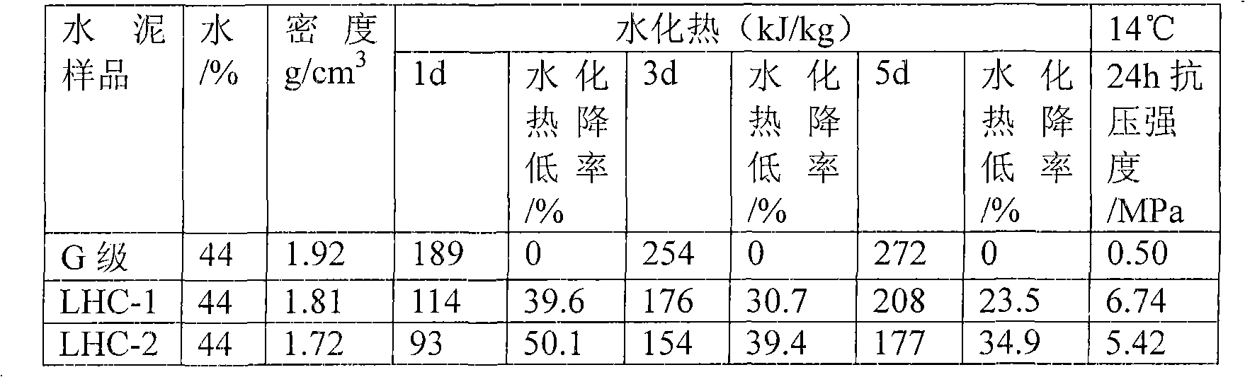
[0022] Prepare cement slurry according to the deep water cementing test standard API 10B-3-2004, and measure the density, heat of hydration, and adiabatic temperature rise of the cement slurry, and compare the heat of hydration with the conventional density G-grade oil well cement slurry under the same conditions, and the measurement results See Table 1 and Figure 1.

[0023] The experimental results show that the heat of hydration of the low-temperature and low-heat-of-hydration cement sy...

Embodiment 2

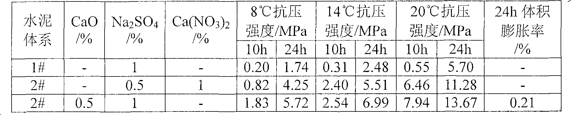
[0026] Example 2, Evaluation of the impact of activators on the compressive strength of the low-temperature and low-hydration heat cementing cement system of the present invention

[0027] Prepare cement slurry according to the deep water cementing test standard API 10B-3-2004, measure the compressive strength of the cement slurry under different temperature curing, and compare the compressive strength with the conventional density G grade oil well cement slurry system under the same conditions, and evaluate The results are shown in Table 2. The experimental results showed that CaO, Na 2 SO 4 , Ca(NO 3 ) 2It can well stimulate the fly ash activity in the low-temperature and low-heat-of-hydration cementing cement system of the present invention, improve the early strength of cement stone, and have good compatibility. At the same time, CaO is a good lattice expansion material. Its slight expansion can not only prevent the shrinkage of cement when it is solidified, but also i...

Embodiment 3

[0032] Example 3, the effect of retarder on the thickening performance of the low-temperature and low-hydration heat cementing cement system of the present invention


PUM

PropertyMeasurementUnit
specific surface areaaaaaaaaaaa
strengthaaaaaaaaaa
strengthaaaaaaaaaa

Abstract

The invention relates to a low temperature and low hydration heat cementing concrete system used in the natural gas hydrate layer cementing field. The objective of the invention is to effectively reduce the heat release of the cement hydration, prevent the hydrate from decomposing because of large heat and reduce the harm of the hydrate to the cementing. The whole performance of the cement under the low heat release condition is improved by adding materials which can reduce the whole hydration heat release of the cement using G grade oil well cement as base material. (1) The proper addition of superfine slag with a specific surface area between 6000 and 12000cm2/g can make sure the strength properties of the early and later stage of the cement. (2) The hydration heat is further reduced by adding fly ash with a lower hydration activity. (3) An amount of gypsum component is added so that the cement paste has certain expansion property at a low temperature to prevent the cement paste shrinking at a low temperature. The low temperature and low hydration heat cementing concrete provided by the invention has an obvious effect for reducing the whole cement hydration heat and a good effect for preventing the deep water hydrate decomposition.

Description

technical field [0001] The invention relates to a low-temperature and low-heat-of-hydration cementing cement system used in the field of natural gas hydrate layer cementing, which is a low-temperature and low-heat-of-hydration cementing system suitable for deep-water hydrate layers, and can also be applied to Onshore permafrost and low temperature surface cementing. Background technique [0002] Today, with the increasing shortage of mineral energy on the earth, the status of natural gas hydrate as a strategic energy source in the 21st century has become increasingly prominent, and it will bring new hope for human beings to provide alternative energy sources. It is estimated that the total amount of natural gas contained in natural gas hydrates in the world is about 1.8×10 16 ~2.1×10 16 m 3 , which is equivalent to twice the total carbon content of proven traditional fossil fuels in the world. Western developed countries such as Europe, America and Japan are competing to ...

Claims


Application Information

Patent Timeline
Patent Type & Authority Applications(China)
IPC IPC(8): C04B28/00C04B18/12C04B18/08C04B22/14
CPCC04B28/026C04B2111/29C09K8/467Y02W30/91C04B18/08C04B18/141C04B20/0092C04B22/143C04B2103/10C04B2103/20
Inventor 王瑞和齐志刚步玉环王成文
Owner CHINA UNIV OF PETROLEUM (EAST CHINA)
Why Eureka
Try Eureka