2.5D graphics rendering system

a graphics rendering and 2.5d technology, applied in video games, indoor games, sport apparatuses, etc., can solve the problems of high bandwidth and transfer rate, 3d graphics data can take time to prepare, etc., and achieve the effect of higher level of detail

Active Publication Date: 2021-04-27
ELECTRONICS ARTS INC
View PDF56 Cites 9 Cited by
  • Summary
  • Abstract
  • Description
  • Claims
  • Application Information

AI Technical Summary

Benefits of technology

[0007]The method of the previous paragraph can include one, any combination of, or all of: the locations of the vertexes of the 2D mesh are locations of parts of a 3D object in the virtual 3D environment projected onto a 2D plane as seen from a viewpoint; the updated locations of vertexes of the 2D mesh for the object are formatted as 2D coordinate locations or changes to previous 2D coordinate locations; executing a video game application; communicating with a server running a host application for the video game application; transmitting at least one of user inputs or viewpoint data to the server, wherein the user inputs or viewpoint data are used to change a viewpoint within the virtual 3D environment; receiving, from the server over the network, a second texture for a second object; storing the second texture into the memory; after receiving the second texture, receiving third frame data; rasterizing a third frame of the video based at least in part on the third frame data; receiving fourth frame data comprising: an identification of the second object, locations of vertexes of a 2D mesh for the second object, and second depth data for the second object; mapping the second texture onto the locations of the vertexes of the 2D mesh for the second object; and rasterizing a fourth frame of a video based at least in part on the second depth data and the second texture mapped onto the locations of the vertexes of the 2D mesh for the object; applying dynamic visual effects to the object.
[0008]Some aspects feature a computing system comprising: a network interface for communicating with a client over a network, and one or more processors. The one or more processors can be configured to execute computer readable instructions to perform steps comprising: hosting a video game application including a 3D environment, wherein objects in the 3D environment are assigned coordinates in 3D space; transmitting, to the client over the network, a 2D texture for an object in the 3D environment; calculating 2D vertexes of a 2D mesh of the object, wherein the 2D vertexes are positioned on a 2D plane as seen from a viewpoint in the 3D environment; transmitting, to the client over the network, the 2D vertexes of the object and depth data for the object; updating a state of the video game application; determining a second viewpoint in the 3D environment; calculating updated 2D vertexes of the 2D mesh of the object, wherein the updated 2D vertexes are positioned on a 2D plane as seen from the second viewpoint; and transmitting the updated 2D vertexes to the client over the network.
[0009]The computer system of the previous paragraph can include processors configured to execute computer readable instructions to perform steps further comprising one, any combination of, or all of: receiving user inputs from the client, and determining the second viewpoint based at least in part on the user inputs; determining a likelihood of a second object in the 3D environment coming into a field of view associated with the viewpoint, and transmitting, to the client, a 2D texture for the second object; progressively transmitting of the 2D texture for the second object to the client over the network while also transmitting data for a plurality of video frames; completing the progressive transmission of the 2D texture for the second object before the second object comes into the field of view; or transmitting a second 2D texture for the object to the client, wherein the second 2D texture has a higher level of detail than the 2D texture. The computer system of the previous paragraph can determine the likelihood based on at least one of: a future location of the viewpoint in the 3D environment; a current location of the viewpoint in the 3D environment; a location of a character of the video game application in the 3D environment; user inputs received from the client; or a position of the second object in the 3D environment.

Problems solved by technology

The 3D graphics data can take time to prepare, and transmitting the data can require a high bandwidth and transfer rates.

Method used


Image

  • 2.5D graphics rendering system
  • 2.5D graphics rendering system
  • 2.5D graphics rendering system

Examples


example 3d

Environment and Corresponding 2.5D Information

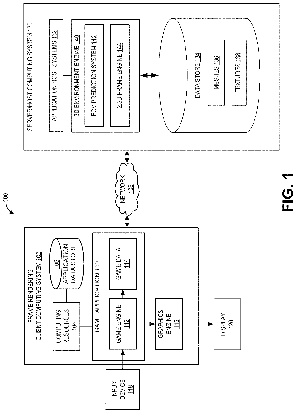
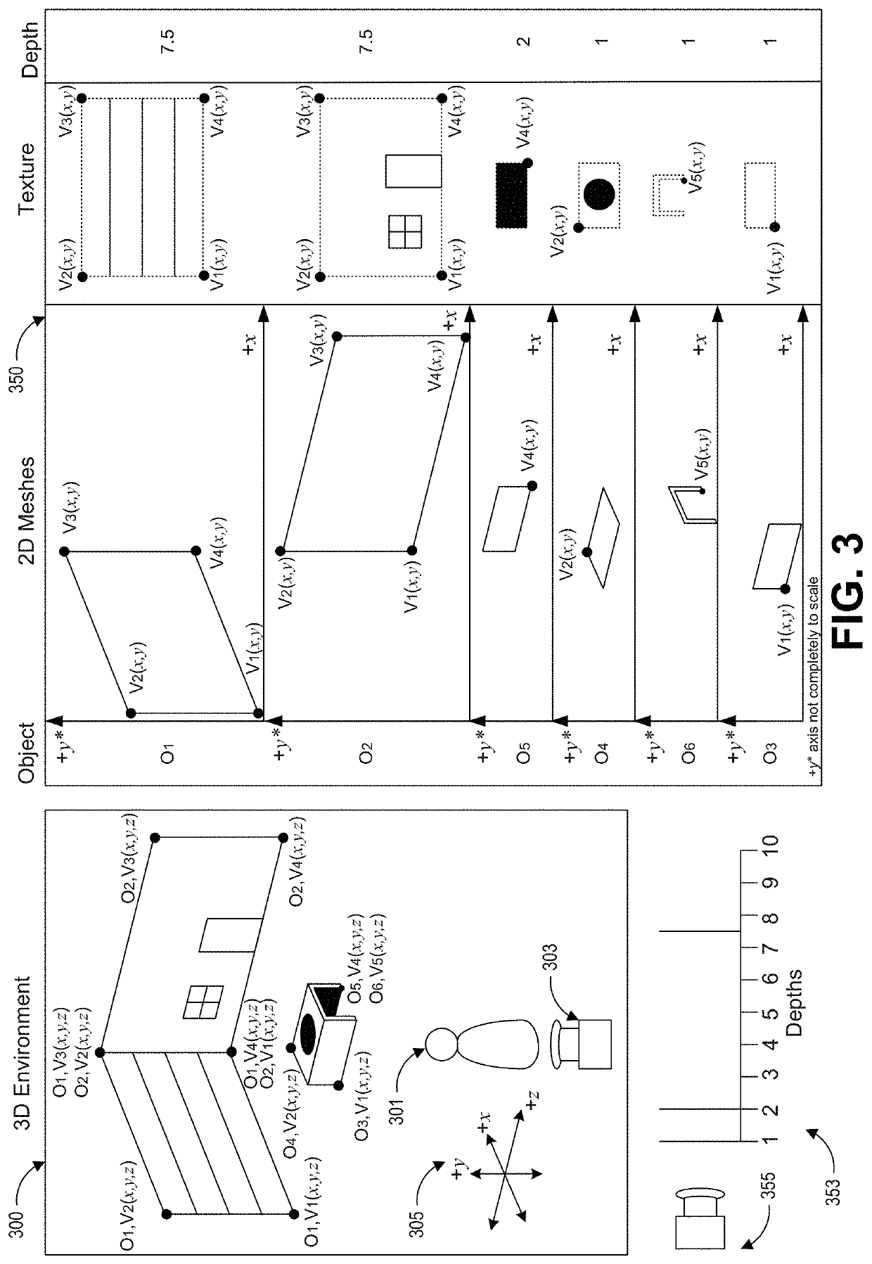
[0072]FIG. 3 shows an example 3D environment 300 and visualization of corresponding 2.5D information. The 3D environment 300 can be simulated by the 3D environment engine 140 as shown in FIG. 1. The 2.5D representation of an image seen from a viewpoint within the 3D environment 300 can be generated by the 2.5D frame engine 144 discussed with respect to FIG. 1.

[0073]The 3D Environment

[0074]The 3D environment 300 shows an inside of a room with a table as seen by a character 301 in the 3D environment 300. The 3D environment 300 includes x, y, and z dimensions as shown by the coordinate system 305. In various embodiments, the coordinate system 305 can be fixed with respect to a stationary point or can be moved relative to a position of a character 301.

[0075]A camera 303 represents a viewpoint in the 3D environment 300 from which a 2.5D representation can be generated. In the illustrated example, the camera 303 represents the viewpoint of the...

example execution

[0120]FIG. 7A shows an example of a rasterized frame 700 of a room, and FIG. 7B shows two 2D textures for rasterizing the frame 700. The frame 700 includes two walls, a box, and a floor. The first 2D texture 705 includes a 2D texture for the walls and floor. The second 2D texture 710 includes a 2D texture for a box.

[0121]A plurality of white vector lines indicates how vertexes of meshes of objects in the 2.5D scene change from one frame to the next as a viewpoint within a corresponding 3D environment moves to the left while rotating to the right. The white vector lines can also indicate how objects move within the environment. In various embodiments, the vectors can be vertexes of mesh boundaries and / or vertexes of mesh interiors.

[0122]The frame 700 is rendered by a client computing system according to the techniques disclosed herein. A one-time data preload (such as described in block 502 of FIG. 5) of about 8.8 MB is transmitted from a server computing system to a client computing...


PUM


Abstract

A graphics rendering system is disclosed for generating and streaming graphics data of a 3D environment from a server for rendering on a client in 2.5D. 2D textures can be transmitted in advance of frames showing the textures. Data transmitted for each frame can include 2D vertex positions of 2D meshes and depth data. The 2D vertex positions can be positions on a 2D projection as seen from a viewpoint within the 3D environment. Data for each frame can include changes to vertex positions and/or depth data. A prediction system can be used to predict when new objects will be displayed, and textures of those new objects can be transmitted in advance.

Description

BACKGROUNDField of the Disclosure[0001]This disclosure relates to graphics processing, video processing, and video communications across a network.Description of the Related Art[0002]Graphics data for 3-dimensional (“3D”) environments can be transmitted from one computer to another. The 3D graphics data can take time to prepare, and transmitting the data can require a high bandwidth and transfer rates.SUMMARY[0003]The systems, methods, and devices in this disclosure each have several innovative aspects, no single one of which is solely responsible for all of the desirable attributes disclosed herein. Details of the one or more implementations of the subject matter described in this specification are set forth in the accompanying drawings and the description below.[0004]Some aspects feature a computing system comprising: a network communications interface configured to communicate via a network with a server that is generating a virtual 3D environment, a memory, and one or more proce...

Claims


Application Information

Patent Timeline
Patent Type & Authority Patents(United States)
IPC IPC(8): A63F13/52A63F13/355A63F13/335
CPCA63F13/355A63F13/335A63F13/52
Inventor BOROVIKOV, IGORSARDARI, MOHSEN
Owner ELECTRONICS ARTS INC
Why Eureka
Try Eureka