Video signal processing

a video signal and processing technology, applied in the field of video signal processing, can solve the problems of a relatively large amount of data involved in the storage of control signals, and achieve the effects of low sensitivity, high detail level, and low sensitivity

Inactive Publication Date: 2005-09-20
KONINKLIJKE PHILIPS ELECTRONICS NV
View PDF19 Cites 5 Cited by
  • Summary
  • Abstract
  • Description
  • Claims
  • Application Information

AI Technical Summary

Benefits of technology

[0007]Preferably, the method also comprises the step of averaging the luminance-derived control signal over a predetermined pixel area. The luminance-derived control signal represents the amount of temporal changes in the video signal at the current image position at high detail level. Advantageously, it has been found that the human visual system has a relatively low sensitivity to the level of detail in the chrominance components of the video signal, compared with sensitivity to detail in the luminance component. Therefore, the luminance-derived control signal is preferably applied on a pixel by pixel basis to the luminance component. However, the average of the luminance-derived control signal is determined over a predetermined area, for use when processing the chrominance components, due to the lower sensitivity. In one perferred embodiment, the luminance-derived control signal is averaged over a 2×2 pixel area, reducing data storage requirements by a factor of 4.

Problems solved by technology

A problem arises in that storage of the control signal involves a relatively large quantity of data.

Method used


Image

  • Video signal processing
  • Video signal processing
  • Video signal processing

Examples


Embodiment Construction

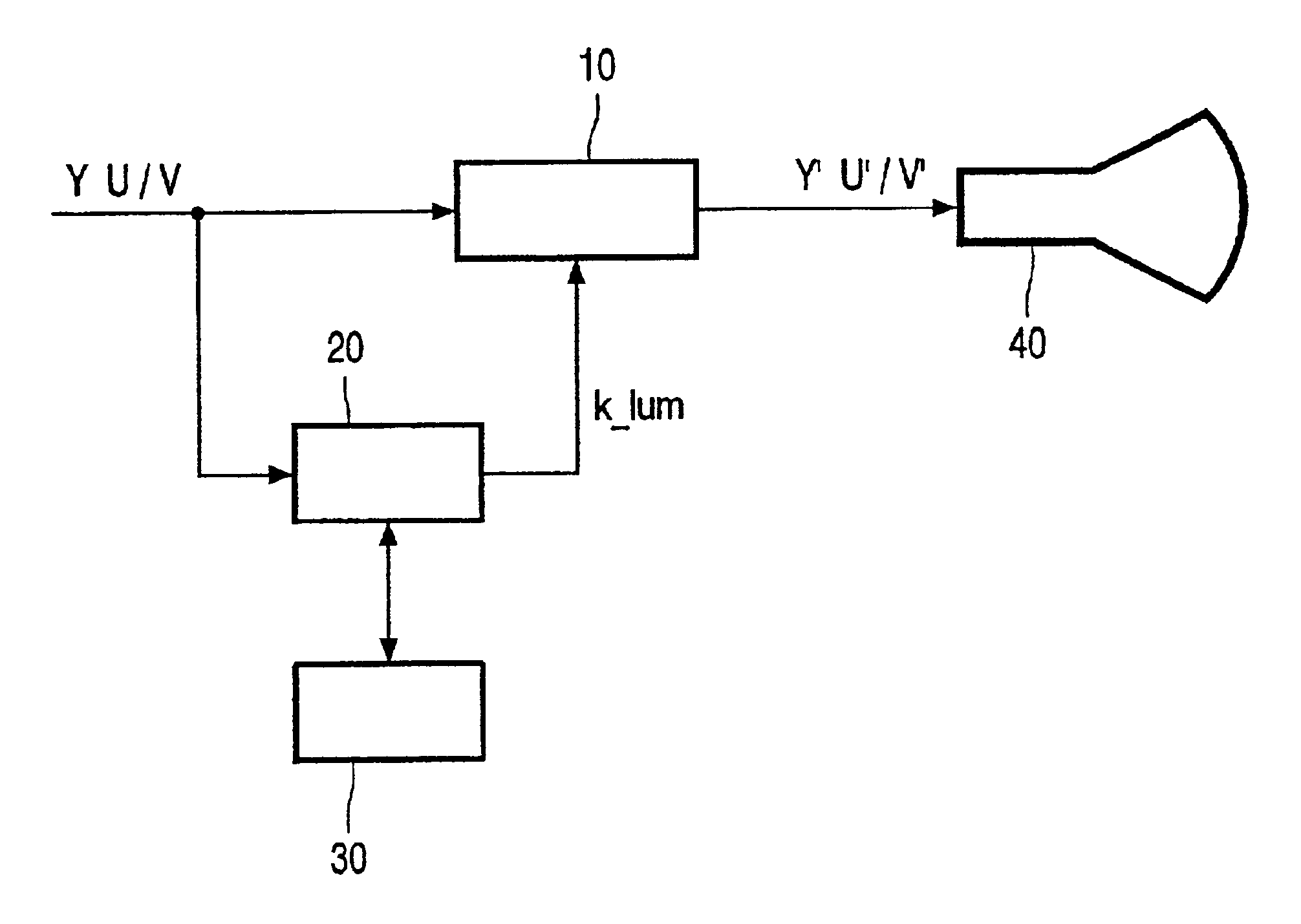
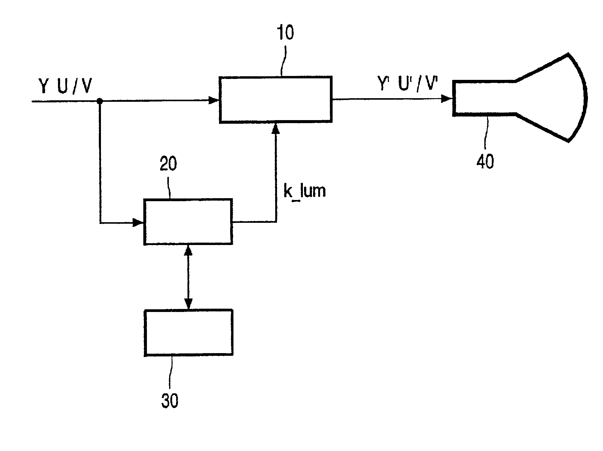
[0010]Referring to the drawing, it is desired to remove noise from a video signal using a noise filter 10. Suitably, the noise filter 10 is a recursive filter. The filter circuit 10 operates sequentially on a luminance component (Y) and then the chrominance components (U / V) of a video signal to produce respective noise filtered signals Y′ and U′ / V′. The noise filter 10 is controlled by a control circuit 20. The control circuit 20 determines the level of noise reduction applied by noise filter 10. The level of noise filtering applied by noise filter 10 is adapted according to the level of motion in the video signal. For example, it is desired to reduce noise filtering applied to areas of the video signal having motion, in order to preserve image quality and avoid introducing additional artefacts like motion blur. By contrast, it is desired to increase noise filtering in areas of the image having relatively low motion. Therefore, the control circuit 20 generates a control signal (k_lu...


PUM


Abstract

A control signal (k_lum) derived from the luminance component (Y) of a video signal is used to adaptively control a temporal noise reduction filter (10) according to the level of motion in a video image. To compress the control signal for storage in a memory (30), the control signal is averaged over each 2×2 pixel area, and then a non-linear compression function is applied. The non-linear compression function preferably selects quantization values of the control signal which correspond to a perceptually substantially linear response in the noise reduction factor (NRF) of the noise filter (10).

Description

FIELD OF THE INVENTION[0001]The present invention relates to a method and apparatus for video signal processing. Also, the present invention relates to a display apparatus comprising such a video signal processing apparatus.BACKGROUND OF THE INVENTION[0002]In one example form of video signal processing, a noise reduction function is applied to reduce noise in a video signal. Noise reduction processing can be applied in a sequential order, first to a luminance component of the video signal, and then to chrominance components of the video signal. Conveniently, the same noise reduction circuit is used for both the luminance and chrominance components of the video signal. Optionally, in luminance controlled processing, a control signal is derived from the luminance component and written to a background memory during processing of the luminance component, and read from the background memory for use during the subsequent processing of the chrominance components. This luminance-derived con...

Claims


Application Information

Patent Timeline
Patent Type & Authority Patents(United States)
IPC IPC(8): H04N9/64H04N5/21
CPCH04N5/21H04N9/646H04N9/77
Inventor HENTSCHEL, CHRISTIANSCHUTTEN, ROBERT JANRIEMENS, ABRAHAM KAREL
Owner KONINKLIJKE PHILIPS ELECTRONICS NV
Why Eureka
Try Eureka