Depressor-adjustment unit and manifold gauge set including the same

a technology of manifold gauge and manifold, which is applied in the direction of instruments, heat measurement, couplings, etc., can solve the problems of gas loss, large amount of gas leaked into the atmosphere, operator burns, etc., and achieve the effect of saving gas

Active Publication Date: 2021-04-27
KANG SUGJAE
View PDF7 Cites 0 Cited by
  • Summary
  • Abstract
  • Description
  • Claims
  • Application Information

AI Technical Summary

Benefits of technology

[0021]According to the present disclosure, when the process of coupling the coupler 1 of the hose 6 of the manifold gauge set to the gas inlet / outlet valve 7 of the heat exchange equipment has been completed, the core-rod depressor 12 pushes the core-rod 9. Thus, this may prevent gas leak due to the gas-tightness between the valve and coupler, thereby protecting an operator from burns and toxic gas poisoning, protecting the environment and saving the gas.
[0022]Further, the position of the core rod of the valve may be easily confirmed from the outside of the gauge hose 6 with the naked eye. Thus, it may be ensured that the core rod reliably reaches to an open state of the valve.

Problems solved by technology

However, a large amount of gas may be leaked into the atmosphere during coupling / decoupling the coupler 1 to / from the gas inlet / outlet valve 7 of the heat exchange equipment such as an air conditioner receiving a high pressure gas therein.
In this process, when there is a high pressure gas inside the equipment, and the equipment is in the open state for a while, a large amount of gas may be released, thereby causing burns of the operator, gas poisoning of the operator, and loss of the gas.
In addition, the core-rod 9 of the gas inlet / outlet valve 7 may not be able to open the core-rod 9 due to an insufficient degree of protrusion of the rod 9.
Thus, it is difficult to safely discharge the exhaust gas from the gas inlet / outlet valve 7 and the residual gas from the manifold gauge set.

Method used


Image

  • Depressor-adjustment unit and manifold gauge set including the same
  • Depressor-adjustment unit and manifold gauge set including the same
  • Depressor-adjustment unit and manifold gauge set including the same

Examples


first embodiment

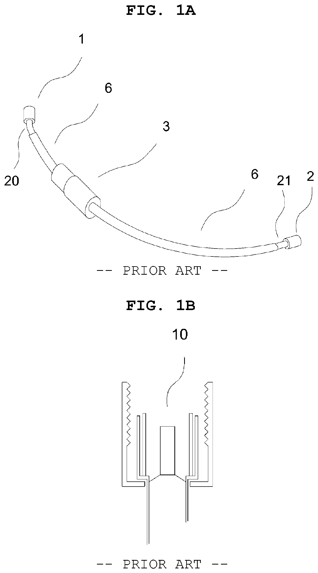
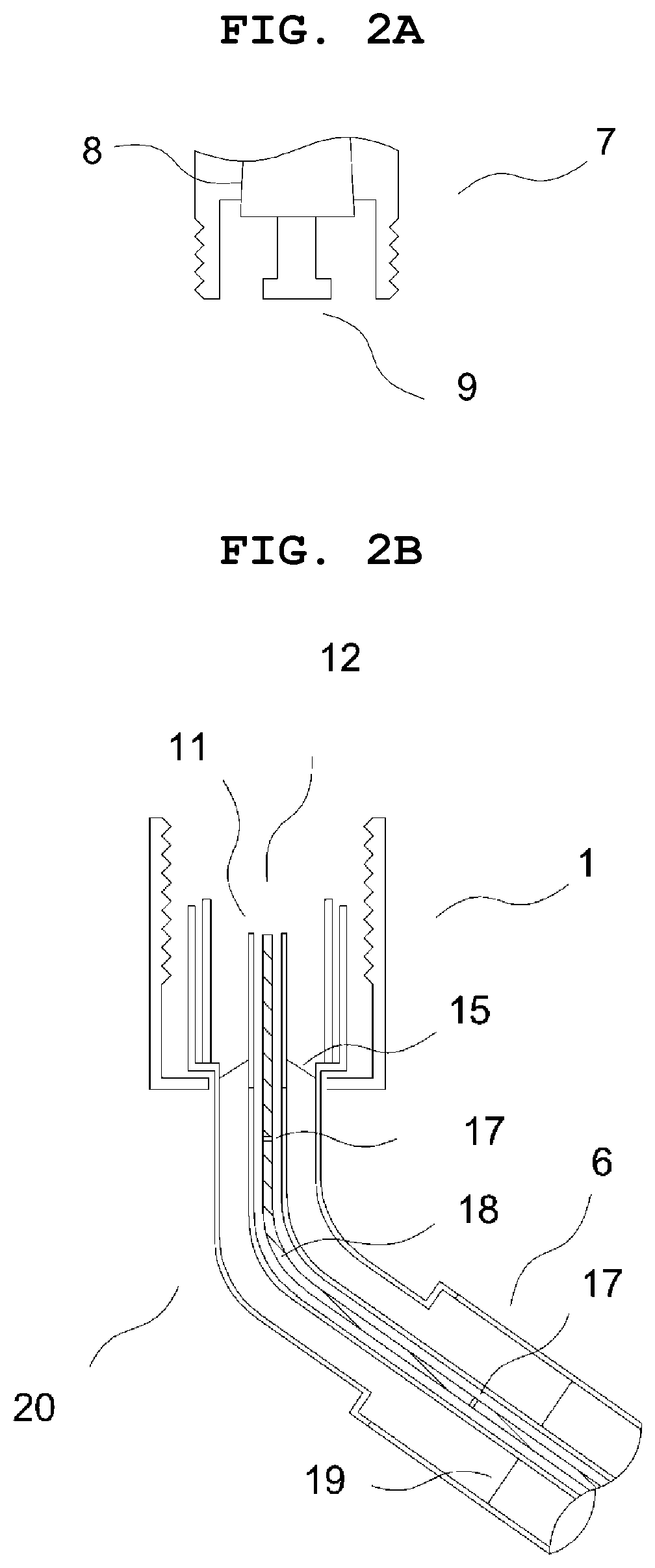
[0093]In a first embodiment, as shown in FIGS. 2A and 2B, the present invention relates to a manifold gauge set including: a hose having a coupler at a distal end thereof, wherein the coupler is detachably coupled to a gas inlet / outlet valve, wherein the valve is opened / closed by a movement of a core-rod resulting from a depressing of a core-rod depressor; the core-rod depressor extending from the coupler into the hose; and a depressor-adjustment unit configured to adjust a position of the depressor, wherein the unit is installed on the hose. This configuration is to prevent the leakage of gas when coupling the coupler 1 of the manifold gauge set to the gas inlet / outlet valve 7 of a heat exchange equipment such as a refrigerator, or, an air conditioner, etc. Herein, the coupler 1 refers to a connection port to the gas inlet / outlet valve / outlet valve 7.

[0094]Specifically, the depressor-adjustment unit 3 installed on the hose near from the coupler 1 divides the hose into two portions....

third embodiment

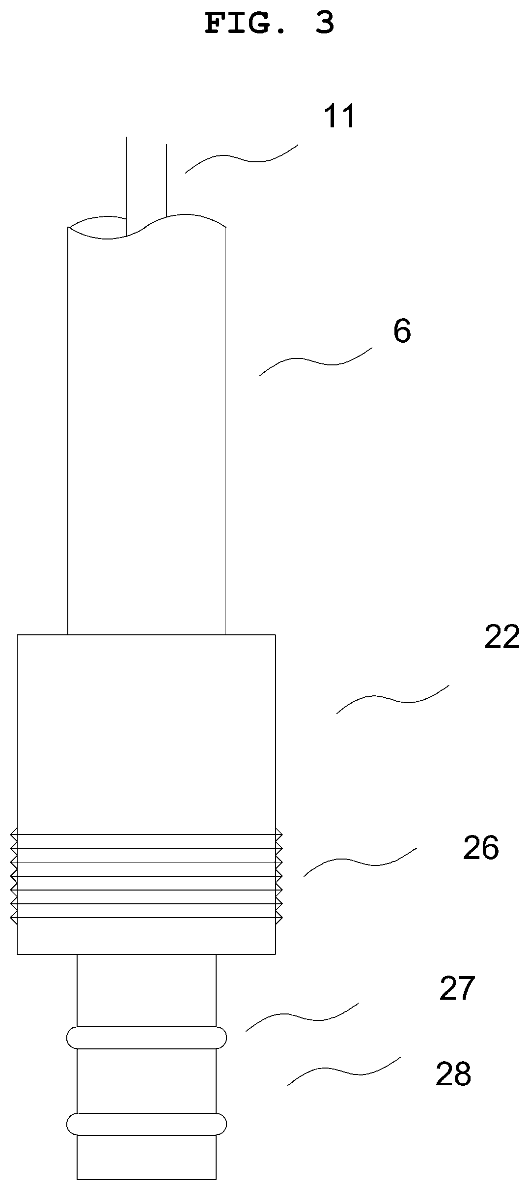
[0097]In a third embodiment, as shown in FIGS. 7A, 7B, and 8, the inner female thread 51 and the second outer male thread 52 are defined on the inner face of the guide tube and on the outer face of the coupler 1 of the core-rod depressor 12, respectively. The inner female thread 51 and the second outer male thread 52 are rotatably engaged with each other. The depressor-adjustment unit 3 is disposed at the middle of the hose 6, thereby dividing the hose 6 into two portions. The first and second plungers 28a, 28b, as shown in FIG. 8, are coupled at the two portions of the hose 6 respectively. The rotatable cylinder portion 55 receives both of the plungers 28 to connect the plungers 28 to each other. The plungers 28 and the rotatable cylinder portion 55 may be rotatably coupled with each other. Each of the plungers 28 and the rotatable cylinder portion 55 may be hollow. A separation preventing protrusion may be provided to prevent separation between the plungers and cylinder portion. F...

fifth embodiment

[0099]In a fifth embodiment, as shown in FIGS. 10A, 10B, and 10C, a manifold gauge set may include a hose 6 having a coupler 1 at a distal end thereof, wherein the coupler is detachably coupled to a gas inlet / outlet valve 7; an elongated hollow tube 88 extending in the hose in a longitudinal direction thereof, wherein an extension axis of the tube is angled with an extension axis of the hose; a movable depressor 12 extending in the tube along the extension axis of the tube; and a depressor-adjustment unit 3 configured to adjust a position of the depressor, wherein the unit is coupled to the hose. A guide tube 11 for guiding the core-rod depressor 12 from the coupler 1 to a distal opening 87 of the elongated hollow tube 88 is provided. The guide tube 11 may be present only in a necessary region. The elongated hollow tube 88 may also act as the guide tube 11 of the core-rod depressor 12. The packing member is disposed between the elongated hollow tube 88 and the core-rod depressor 12 ...


PUM

PropertyMeasurementUnit
lengthaaaaaaaaaa
elastic forceaaaaaaaaaa
timeaaaaaaaaaa

Abstract

In accordance with the present disclosure, leak of gas is suppressed when a coupler of a manifold gauge set including a gas hose is detached to a gas inlet / outlet valve of a thermal exchange equipment. To this end, the set includes a core-rod depressor extending from the coupler into the hose, and a depressor-adjustment unit disposed on the hose to adjust a position of the core-rod depressor.

Description

TECHNICAL FIELD[0001]The present disclosure relates to a depressor-adjustable unit and a manifold gauge set comprising the same. In a prior art, a coupler 1 of the manifold gauge set is coupled to a gas inlet / outlet valve 7 installed in a heat exchange equipment such as a refrigerator, an air conditioner, etc. in order to inject / discharge / inspect a refrigerant. However, when the coupling has not been completed, a fixed core depressor 10 inside the coupler 1 starts to push a core-rod of the gas inlet / outlet valve 7. Thus, a large amount of the refrigerant may leak into the atmosphere. In accordance with the present disclosure, to prevent this, the fixed core depressor 10 of the coupler 1 is replaced with an extendable or retractable core-rod depressor 12 to push the core-rod while the coupling has been completed.RELATED ART[0002]Conventionally, a manifold gauge set includes a gauge body and a number of hoses 6, each hose 6 including a coupler 1 fastened thereto. The coupler 1 include...

Claims


Application Information

Patent Timeline
Patent Type & Authority Patents(United States)
IPC IPC(8): F16L37/086G01K1/14G01D11/30F16C1/22F16K31/46G01L19/00F16L29/00G01F15/18F16L37/413F16L37/44
CPCF16L37/086F16C1/226F16K31/465F16L29/007F16L37/413G01D11/30G01F15/18G01F15/185G01K1/14G01L19/00F16L37/44G01L19/003F16L37/08F16L37/28
Inventor KANG, SUGJAE
Owner KANG SUGJAE
Why Eureka
Try Eureka