Electro-mechanical valve servo apparatus for tool-free retrofit installation

a technology of electronic mechanical valves and retrofit installations, applied in the direction of valve details, valve arrangements, gripping heads, etc., can solve the problems of malfunctioning valve actuators, existing valve robot hands cannot adapt to ball valves of different specifications, etc., to reduce manufacturing difficulty, simple realization, and improved manufacturing efficiency

Active Publication Date: 2021-05-04
SZE CHUN KUEN
View PDF6 Cites 5 Cited by
  • Summary
  • Abstract
  • Description
  • Claims
  • Application Information

AI Technical Summary

Benefits of technology

[0009]In the above-mentioned scheme, it provides a possible realization of the first centering sleeve and the driving fork in an unoperated state, or when only the driving fork should be configured to sleeve on the screw cap, the relative position relationship of the first centering sleeve and the driving fork, wherein the above design allows protection of the first centering sleeve and the first return spring connected to it. At the same time, when adapting to a screw cap of another dimension (such as the above-mentioned second screw cap), the first centering sleeve can be quickly sleeved on the screw cap, improving the efficiency of the installation of the valve robot hand on the ball valve.
[0035]In the above-mentioned scheme, it provides a specific structure of a gripper that can realized. Through the first assembly rod and the second assembly rod, the first screw hole and the second screw hole in the gripper are conveniently and simply realized, thereby effectively improving the efficiency of manufacturing and reducing the difficulty of manufacturing. Moreover, due to the application of left-handed and right-handed threads, it allows the adjusting screw rod to quickly cooperate with the first screw hole and the second screw hole. This reduces the clamping and releasing time of the first clamping piece and the second clamping piece of the gripper.

Problems solved by technology

However, existing valve robot hands cannot adapt to ball valves of different specifications.
Furthermore, existing valve actuator is mounted on a pipe by a metal hoop ring hose clamp located at only one side of the valve, and counter force from the valve will cause loosening and shifting of the clamp and will eventually lead to malfunctioning of the valve actuator because the valve actuator is no longer aligned properly with the valve for normal operation.

Method used


Image

  • Electro-mechanical valve servo apparatus for tool-free retrofit installation
  • Electro-mechanical valve servo apparatus for tool-free retrofit installation
  • Electro-mechanical valve servo apparatus for tool-free retrofit installation

Examples


first embodiment

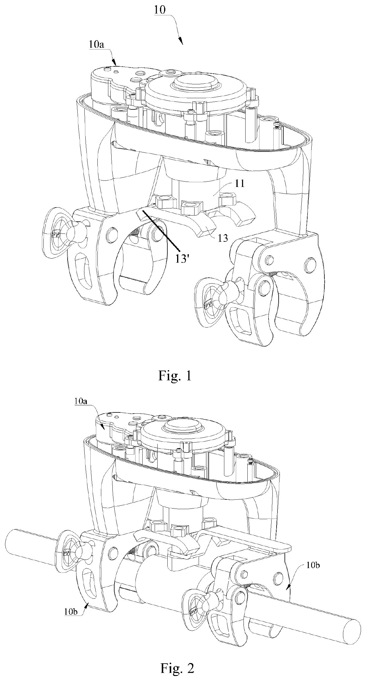
[0062]FIGS. 1-8 show an electro mechanic valve servo apparatus or valve robot hand 10 of the present application. The valve robot hand 10 can adapt to ball valves of a variety of dimensions. It can make the rotating axis of the power output of the valve robot hand 10 to be lying on the same straight line as the rotating axis of a ball valve handle.

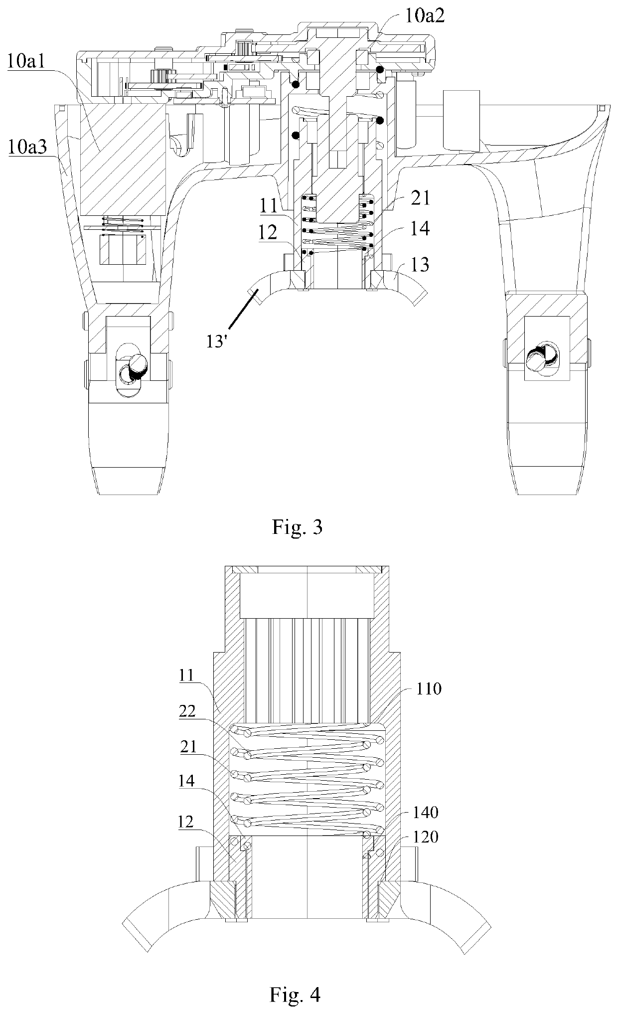
[0063]Referring to FIG. 1, FIG. 2, and FIG. 3, FIG. 1 shows a specific structure of the valve robot hand 10 in a first perspective, FIG. 2 shows a specific structure of the valve robot hand 10 in a second perspective, and FIG. 3 shows a specific structure of the valve robot hand 10 in a third perspective.

[0064]Among them, FIG. 2 shows an application scenario diagram of the valve robot hand 10 of the first embodiment. It can be seen from FIG. 2 that the valve robot hand 10 is secured to a pipe, which includes a ball valve. The valve robot hand 10 is configured to control the rotation of the handle of the ball valve.

[0065]It can be seen from...

second embodiment

[0116]FIGS. 14 and 15 show the top and bottom perspective views of an assembly of the transmitting and centering sleeves of the valve robot hand having only one driving fork 13.

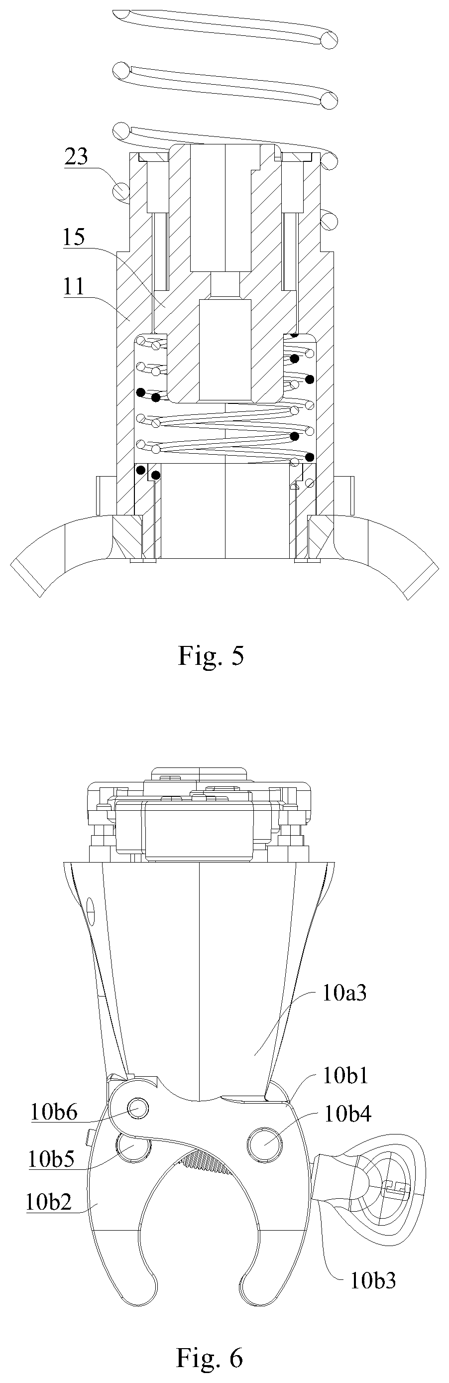
[0117]FIG. 16 is an exploded view of the components of the assembly of the transmitting and centering sleeves of the second embodiment of the valve robot hand having only one driving fork 13. As shown in FIG. 16, the assembly includes transmitting sleeve 11, annular top cover 11a for covering a top end of the transmitting sleeve 11, first centering sleeve 12, second centering sleeve 14, transmitting shaft 15, first return spring 21, second return spring 22, third return spring 23, and only one driving fork 13 which is used to couple with and rotate the handle of a ball valve of a pipe.

[0118]The above are only preferred embodiments of the present application, and are not used to limit the present disclosure. For a technical person skilled in the art, the present disclosure may have various modifications and ch...


PUM


Abstract

A valve robot hand includes a driving device, a transmitting sleeve, a first return spring, a first centering sleeve configured to sleeve on a screw cap of a valve handle, and a driving fork configured to couple with the valve handle. A lower end of the transmitting sleeve is connected with the driving fork. The driving fork is provided with a first through-hole configured to sleeve on the screw cap of the valve handle. The first through-hole is coaxial with the transmitting sleeve. The driving fork is sleeved on the first centering sleeve through the first through-hole such that the first centering sleeve is capable of moving in the transmitting sleeve along its axial direction. The first return spring is configured to exert a downward elastic force on the first centering sleeve.

Description

CROSS REFERENCE TO RELATED APPLICATIONS[0001]This is a continuation-in-part application of PCT Application No. PCT / CN2019 / 107058 filed on Sep. 20, 2019, which claims priority of Chinese patent application No. 201910505506.0 filed at the China National Intellectual Property Administration on Jun. 12, 2019, entitled “Valve Robot Hand”. The contents of the applications are incorporated herein by reference in their entireties.TECHNICAL FIELD[0002]The present application relates to the field of valve control technology, and particularly relates to an electro mechanic valve servo apparatus, or a valve robot hand.BACKGROUND TECHNOLOGY[0003]A valve robot hand is a machinery that controls the opening and closing of a fluid ball valve for domestic and industrial use. However, existing valve robot hands cannot adapt to ball valves of different specifications. Furthermore, existing valve actuator is mounted on a pipe by a metal hoop ring hose clamp located at only one side of the valve, and cou...

Claims


Application Information

Patent Timeline
Patent Type & Authority Patents(United States)
IPC IPC(8): F16K31/05B25J15/00B25J15/02
CPCF16K31/055B25J15/0028B25J15/02B25J15/0033F16K31/04B25J11/00B25J15/00
Inventor SZE, CHUN KUEN
Owner SZE CHUN KUEN
Why Eureka
Try Eureka