In-situ device for collecting minerals

a monitoring device and mineral technology, applied in the field of in-situ monitoring devices, can solve the problems of high cost and logistical challenges of traditional drilling techniques, and achieve the effects of cost saving, reliable data, and low cos

Active Publication Date: 2021-05-11
ARCADIS U S
View PDF2 Cites 2 Cited by
  • Summary
  • Abstract
  • Description
  • Claims
  • Application Information

AI Technical Summary

Benefits of technology

[0007]It is one aspect of embodiment of the present invention to provide a device for monitoring the formation of target minerals in-situ, which is sometimes referred to as a “mineral trap.” Mineral traps configured to collect minerals from an aquifer may be seamlessly integrated into a broad range of remediation programs in simple or complex geologic environments to provide more reliable data than current techniques at a low cost. Because of the cost savings, mineral traps can facilitate the increased utility of mineralogical data to support a broad range of technical and regulatory objectives at sites where traditional approaches to data are considered cost prohibitive. M

Problems solved by technology

However, development of a high-quality data set to support these technical needs comes with the high

Method used


Image

  • In-situ device for collecting minerals
  • In-situ device for collecting minerals
  • In-situ device for collecting minerals

Examples


Embodiment Construction

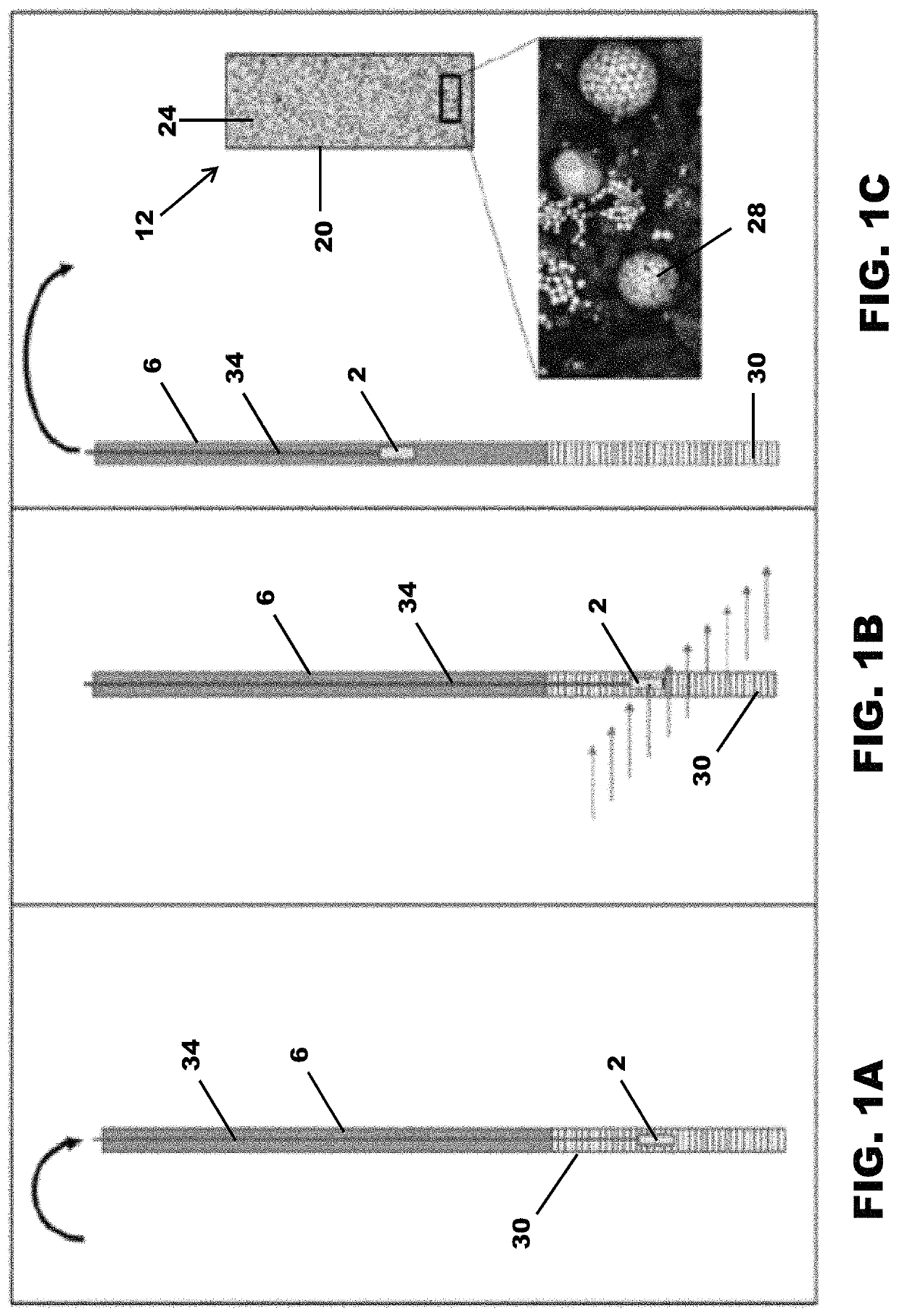
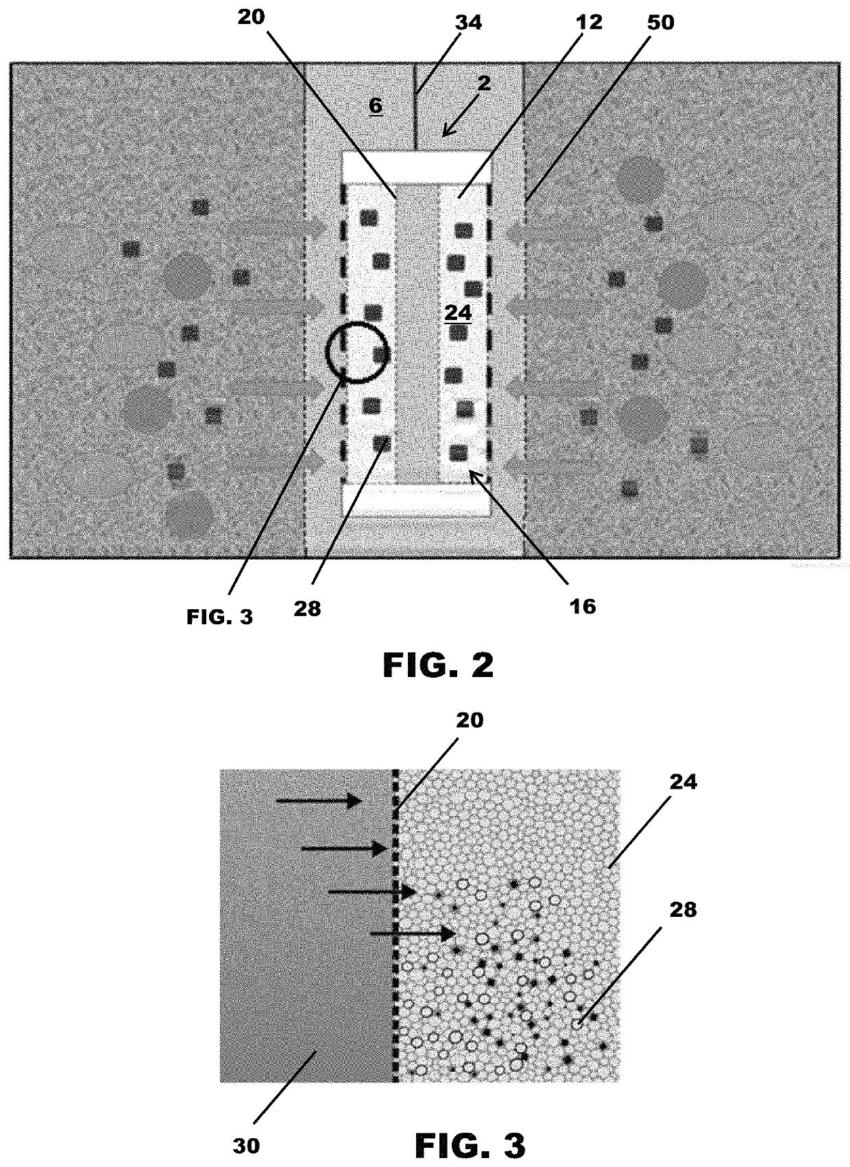
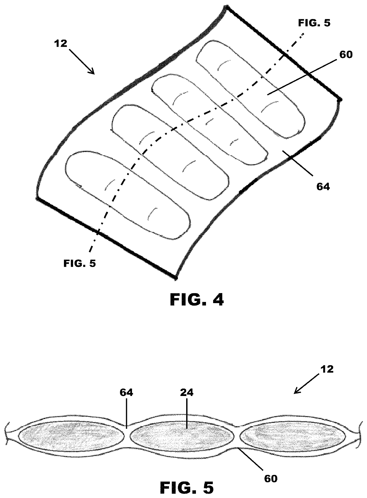
[0036]FIGS. 1A-1C are schematics of a mineral trap assembly 2 of one embodiment of the present invention deployed within a standard 2-inch diameter monitoring well 6. The mineral trap assembly 2 is generally comprised of a mineral trap 12 positioned within a housing 16. The mineral trap is further compromised of a fluid-permeable outer member, such as mesh 20, that contains media 24 designed to capture precipitated minerals 28 from groundwater in an aquifer 30. In operation, the mineral trap assembly 2 is held in the aquifer by a line 34. As groundwater infiltrates through mineral trap media 24, mineral grains precipitate solid-phase 28 and / or coatings that are retained. Thus, the mineral trap assembly 2 of one embodiment of the present invention is a passive sampling device for monitoring the formation of reactive minerals in anaerobic in-situ reactive zones (IRZs) 40. The media 24 can be a non-reactive medium (e.g. silica sand), a reactive medium (e.g. iron oxide sand or site soil...


PUM


Abstract

An in-situ monitoring tool is provided that is compromised of a non-reactive medium, a reactive medium, or a combination thereof, contained in a water-permeable mesh. The tool is placed in an aquifer for a predetermined amount of time to allow the medium(s) to act as a substrate that collects minerals from the aquifer for analysis.

Description

[0001]This application is a continuation of U.S. patent application Ser. No. 16 / 180,443 filed on Nov. 5, 2018 which claims benefit of U.S. Patent Application Ser. No. 62 / 720,765, filed Aug. 21, 2018, the entirety of which are both incorporated by reference herein.FIELD OF THE INVENTION[0002]Embodiments of the present invention generally relate to an in-situ monitoring device adapted for insertion into an aquifer, such as a well. The monitoring tool collects minerals from the aquifer that are later tested to ascertain water quality.BACKGROUND OF THE INVENTION[0003]The standard approach to characterizing minerals at a field site being remediated involves soil sampling at depth via drilling, which can be costly and technical challenging. For a site underlain by competent or fractured rock, these challenges are more significant. While confirmatory subsurface soil / rock sampling is a component of many remediation programs, extensive or repeated drilling events are often prohibitively expe...

Claims


Application Information

Patent Timeline
IPC IPC(8): G01N1/10E21B43/08G01N33/18
CPCG01N1/10E21B43/082E21B43/084G01N33/1853E02D1/06G01N1/12
Inventor ULRICH, SHANNONTILTON, JENNIFER P.FORD, JEFFERY P.LILES, DAVIDDIVINE, CRAIGJUSTICA-LEON, SHANDRAGILLOW, JEFF
Owner ARCADIS U S
Why Eureka
Try Eureka