
Tactile cerclage wire and cable passer and methods of use

a technology of cerclage wire and cable, applied in the field of medical applications, can solve the problems of conventional cerclage passers associated with morbidity/complication, soft tissue prevents adequate tightening of wires or cables, and interposition of soft tissue poses a safety risk, so as to increase the flexibility of the appendage guide and reduce the thickness

Active Publication Date: 2021-06-01
SKINNER HARRY B
View PDF22 Cites 0 Cited by
  • Summary
  • Abstract
  • Description
  • Claims
  • Application Information

AI Technical Summary

Benefits of technology

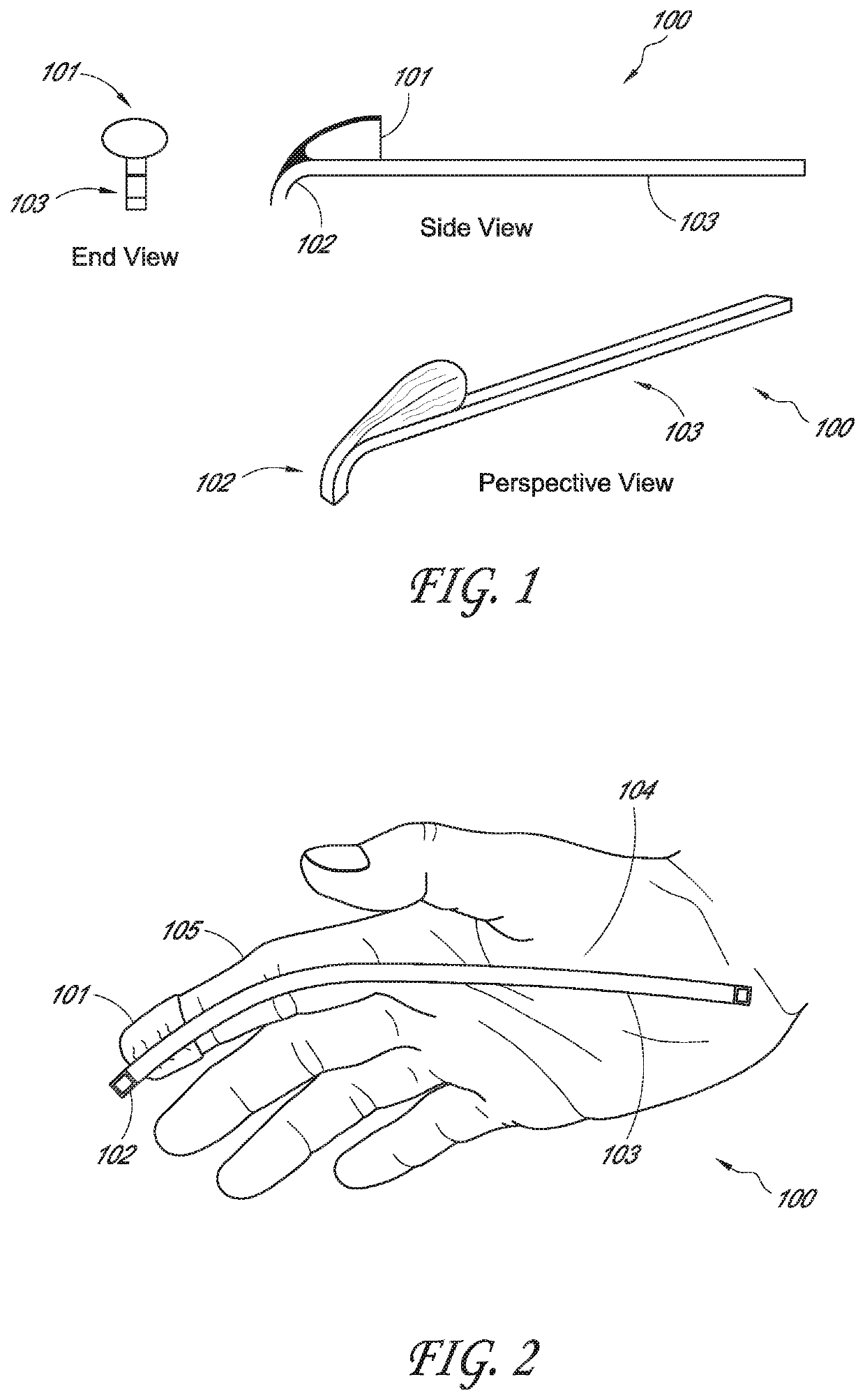
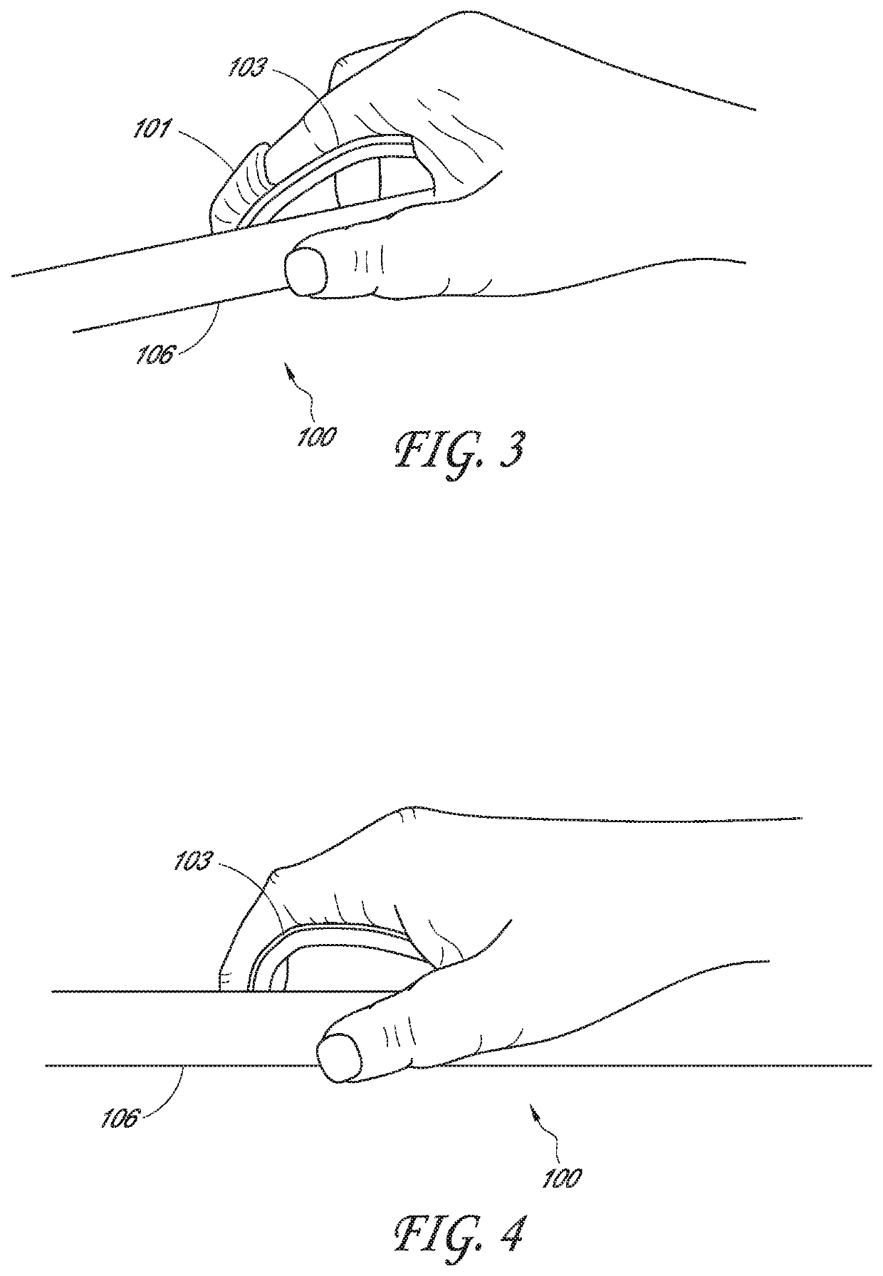
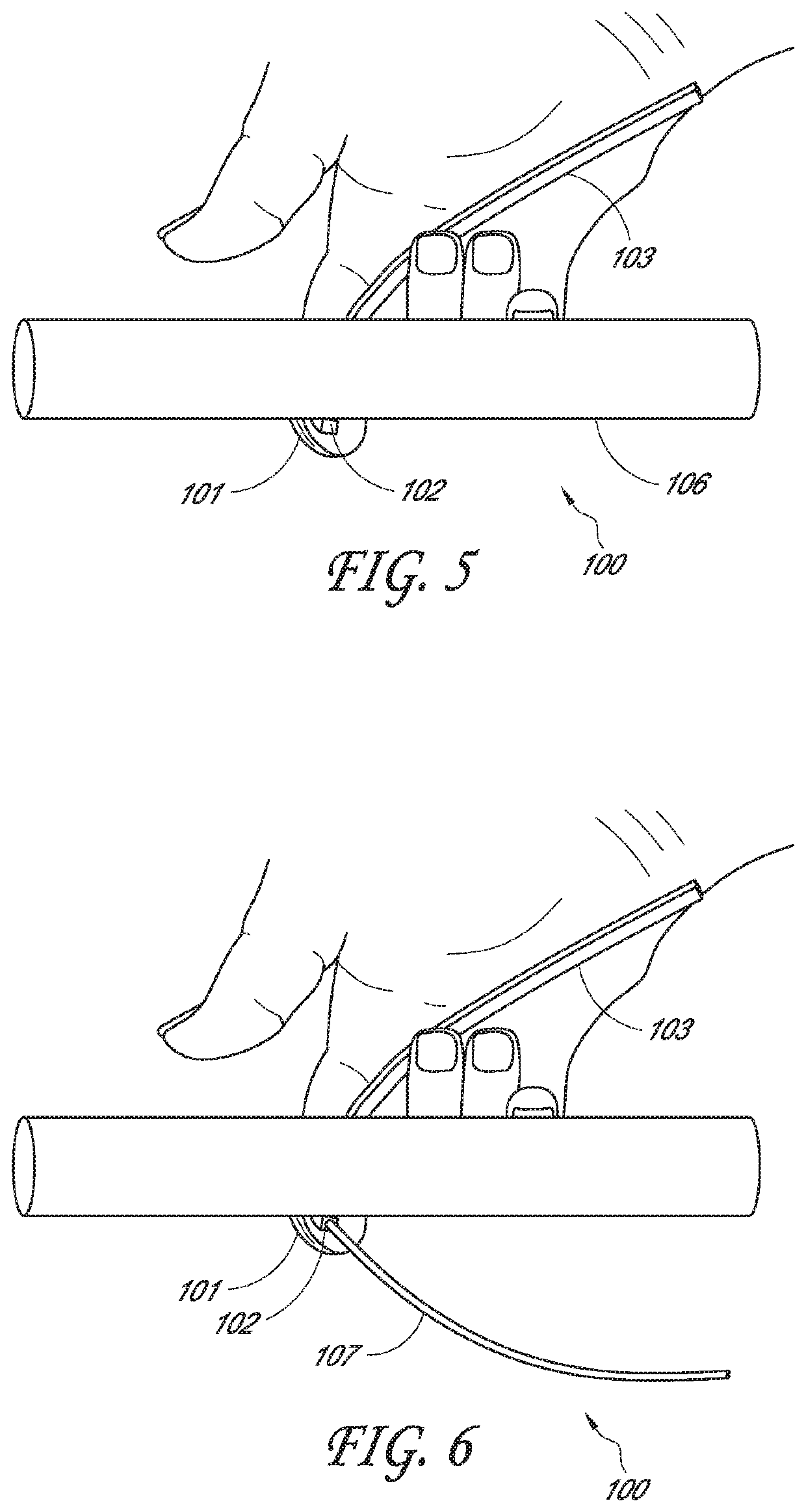
[0004]In some embodiments, disclosed herein is a cerclage wire or cable passer that can include any number of features disclosed herein. The passer can include any number of the following, including: a flexible tube that includes a first surface and a second surface opposite the first surface. The first surface can be substantially flat and configured to contact an outer surface of the bone and lie flat on the bone as it is passed around the bone. The flexible tube can further include a proximal end, a distal end, a lumen configured to house a wire or cable therethrough, and an elongate body therebetween. The distal end can include a curved shape. The passer can also include an appendage guide that includes an open proximal end and an open or closed distal end. The appendage guide can be directly adjacent the second surface of the flexible tube. The appendage guide can be configured to house the distal phalanx of a finger of an operator. The distal end of the appendage guide can define the transition from the elongate body of the flexible tube to the curved distal end of the flexible tube extending distally past the distal end of the appendage guide. In some embodiments, the passer can be configured to be sufficiently flexible to conform to the radius of curvature of the bone from pressure from the finger. In some embodiments, the appendage guide comprises a smooth surface radially inward and / or outward surface. In some embodiments, the appendage guide is configured to allow passage of the guide through tissue, and sized to hold the distal phalanx of the finger securely and allow tactile appreciation for a location of the curved distal end of the flexible tube. In some embodiments, the distal end of the flexible tube comprises a constant, or variable radius of curvature. The flexible tube can have a length sufficient that the finger in the appendage guide does not completely encircle the bone, to allow retrograde passage of the wire / cable. The bone could be, in some cases, a tibia, fibula, humerus, femur, or other desired bone. The cerclage passer can include a hinge. The appendage guide can include a slot and / or an area of reduced thickness to increase flexibility of the appendage guide.
[0005]The flexible tube can also be of sufficient rigidity that the guiding finger can discern the position of the curved distal end of the flexible tube against the bone by friction, preventing soft tissue interposition between the cerclage passer and the bone. The appendage guide can include a clip in some cases. The flexible tube can include a variety of cross-sections, including a rectangular, square, semi-circular (including but not limited to semi-oval), or other cross-sections. The flexible tube can include a slot to increase flexibility of the flexible tube.

Problems solved by technology

Soft tissue prevents adequate tightening of the wire or cable.
In addition, interposition of soft tissue poses a safety risk as that soft tissue may include vital structures such as nerves or blood vessels.
In some cases, conventional cerclage passers can be associated with morbidity / complications such as vascular or nerve injury caused because the cerclage or wire is passed too far away from the surface of the bone, and blood vessels, nerves, and other structures can be impinged by the cerclage or wire.

Method used


Image

  • Tactile cerclage wire and cable passer and methods of use
  • Tactile cerclage wire and cable passer and methods of use
  • Tactile cerclage wire and cable passer and methods of use

Examples


Embodiment Construction

[0019]Cerclage devices for passing a wire or cable around a bone have been in surgical practice for many years. Many of these devices are rigid “C” or “S” shaped tubes with a handle. These can be clumsy and difficult to use because of their rigidity. In order to accommodate large and small bones, they have a much larger radius of curvature than the bone and they are, therefore, difficult to keep the tip close to the bone to avoid soft tissue interposition. If the cerclage passer has a small arc, it can tend to trap soft tissue because it may not be able to reach all the way around the bone. If the cerclage passer has a large arc, it may have to be turned sideways, parallel to the length of the bone to get started around the bone, requiring a more extensive dissection.

[0020]Other forms of passers incorporate minimally invasive devices which can depend on a coil of wire, tube, or a spring plate to conform to the shape of the bone as it is passed into the wound. These devices may have ...


PUM


Abstract

A surgical device is disclosed which provides a safe means of passing a cerclage wire around a bone and the technique for accomplishing this task is described. This device uses the tactile sensation of the human hand to achieve appropriate placement of the cerclage wire. Thus, Irregularities in the bone fragments of a fracture or bone graft augmenting a fracture can safely be encircled and secured. The device permits retrograde placement of the cerclage wire compatible with available manufactured devices.

Description

PRIORITY CLAIM[0001]This application is the U.S. National Phase under 35 U.S.C. § 371 of International Application No. PCT / US2017 / 051910, filed Sep. 15, 2017, which claims the benefit as a nonprovisional application of U.S. Prov. App. No. 62 / 396,197 filed on Sep. 18, 2016, which is hereby incorporated by reference in its entirety.BACKGROUNDField of the Invention[0002]Certain embodiments of the invention relate to medical applications, including orthopedic surgery, but also in any area of surgery (including veterinary medicine) where a wire needs to be passed around a bone (or other body structure), such as fracture care or in the treatment of major joint reconstruction, especially revisions.Description of the Related Art[0003]A cerclage device is used by orthopedic surgeons and other practitioners of the healing arts to allow a bone to be encircled and held together with a wire or cable. Such devices can secure bone fracture fragments, and / or reinforce a long bone from hoop stress. ...

Claims


Application Information

Patent Timeline
Patent Type & Authority Patents(United States)
IPC IPC(8): A61B17/88A61B17/82A61B17/56A61B17/00A61B17/90
CPCA61B17/8861A61B17/56A61B17/82A61B2017/00424A61B2017/00438A61B2017/90A61B17/90
Inventor SKINNER, HARRY B.
Owner SKINNER HARRY B
Learn More