Detention pond method

a technology of detention pond and pond body, which is applied in the direction of sewer system, sewage draining, construction, etc., can solve the problems of not allowing permanent pooling of water, high cost of development land, and high cost of land, and achieve the effect of greater detention pond capacity

Active Publication Date: 2021-06-08
ADAMEK FRANK CHARLES +1
View PDF22 Cites 0 Cited by
  • Summary
  • Abstract
  • Description
  • Claims
  • Application Information

AI Technical Summary

Benefits of technology

The patent aims to increase the capacity of a detention pond without buying more real estate. It proposes to utilize the natural slope of the geographic area to increase the depth of the pond. The technical effect is a larger detention pond capacity without additional land acquisition.

Problems solved by technology

Detention ponds are designed to release all captured runoff over time, and do not allow for permanent pooling of water.
This land is called “expensive” as a detention pond would only be constructed in a developed area which you want to protect, and developed land is expensive.
With the volume of rainfall in Houston and the low grade to the slope, many areas are subject to flooding, and have been since urbanization happened in the 19th century (if not before).
Increasing the channel size and detention ponds have been tried for many years with the present result being that the existing detention ponds are over-run with flood waters in a heavy rain.
The resulting use of conventional detention ponds has not solved the problem and massive flooding damage continues to happen in Houston.

Method used


Image

  • Detention pond method
  • Detention pond method
  • Detention pond method

Examples


Embodiment Construction

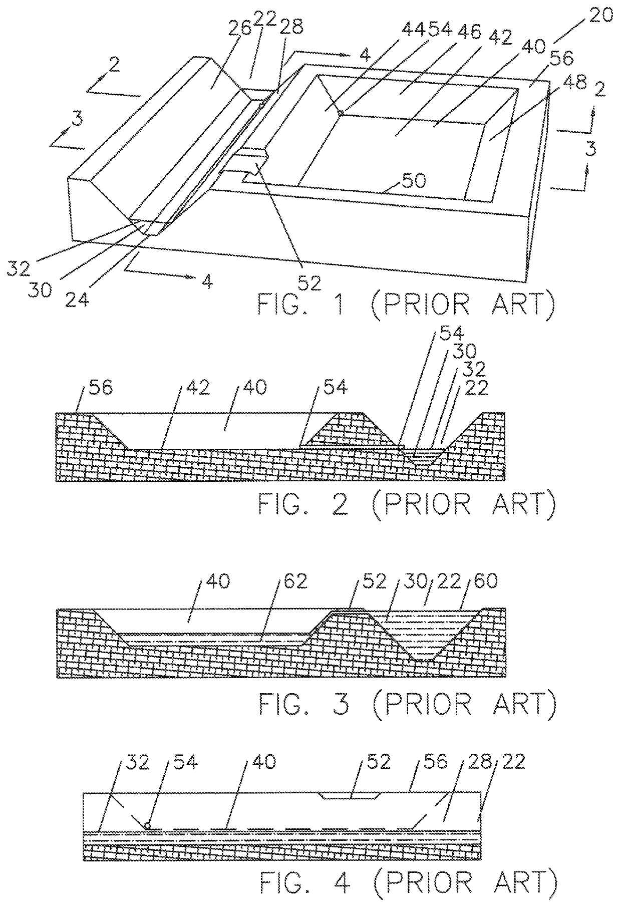
[0019]FIG. 1 is a perspective view of a detention pond area 20 showing a river, stream, or bayou 22 having a bottom 24, sides 26 and 28, and water 30 flowing in the river, stream, or bayou. The water flowing in the river, stream, or bayou is of an elevation 32 in this figure. The detention pond 40 has a bottom 42, sides 44, 46, 48, and 50 (not seen), a weir 52 to direct near flooding waters to be detained into the detention pond 40 and a drain-pipe 54 to slowly release the detained waters back into the river, stream, or bayou 22. Ground level 56 is shown around the river, stream, or bayou and detention pond.

[0020]Referring now to FIG. 2 taken along lines “2-2” of FIG. 1, drain-pipe 54 is shown to connect the bottom 42 of the detention pond 40 with the river, stream, or bayou 22 above the elevation 32 of the waters 30 during the normal flow of the river, stream, or bayou.

[0021]Referring now to FIG. 3 taken along lines “3-3” of FIG. 1, the elevation 60 of the water 30 in the river, st...


PUM


Abstract

A detention pond for the passive temporary storage of detained water during a potential flooding event near a river, stream or bayou where the depth and therefore the volume of the detention pond is not set by the elevation of the normally flowing water in said river, stream or bayou adjacent detention pond but rather the drain line connects to the river, stream or bayou downstream of the detention pond where the elevation is at a lower level, allowing the detention pond to be dug deeper and therefore of proportionately greater volume.

Description

TECHNICAL FIELD[0001]This invention relates to the method of minimizing flooding by the use of detention ponds.BACKGROUND OF THE INVENTION[0002]A detention pond is an area excavated near river, steam stream, or bayous to protect against areas flooding, generally in urban areas. Detention ponds receive potentially flooding waters and hold it for release at a predetermined rate. Detention ponds are designed to release all captured runoff over time, and do not allow for permanent pooling of water. This is generally done with a simple pipe connecting the bottom of the detention pond to the river, stream, or bayou or in other words with a drain-pipe.[0003]The depth of the detention pond is set by the elevation of the water in the river, stream, or bayou during normal flow or the average flow during a non-flooding event. Water typically enters a detention pond when the river, stream, or bayou is reaching or near flood stage and simply flows over a weir to fill the detention pond.[0004]The...

Claims


Application Information

Patent Timeline
IPC IPC(8): E03F1/00E02B3/02E03F5/10
CPCE03F1/001E03F5/103E03F5/107E02B3/02E03F5/106
Inventor ADAMEK, FRANK CHARLESBAUGH, BENTON FREDERICK
Owner ADAMEK FRANK CHARLES
Why Eureka
Try Eureka