Pinch clamp device

a technology of a clamp and a clamping device, which is applied in the direction of other medical devices, catheters, valves, etc., can solve the problems of unintentional disengagement of the clamp and the challenges that remain, and achieve the effects of preventing abrasion or irritation to the patient, increasing friction, and increasing friction

Active Publication Date: 2021-06-22
BECTON DICKINSON & CO
View PDF94 Cites 4 Cited by
  • Summary
  • Abstract
  • Description
  • Claims
  • Application Information

AI Technical Summary

Benefits of technology

[0006]The present invention relates to pinch-style clamps that are designed for use in clamping or occluding plastic tubing, such as intravenous tubing. The pinch clamp of the present invention addresses and overcomes various difficulties known to exist in prior art pinch clamps. For example, some embodiments of the present invention comprise a soft material applied to various surfaces of the pinch clamp to 1) prevent abrasion or irritation to the patient, 2) increase friction between the pinch clamp and the user operating said pinch clamp, 3) increase friction between engaged surfaces of the pinch clamp to prevent premature or unintended disengagement of the clamp, and 4) increase friction between the outer surfaces of the tubing and the clamping surfaces of the clamp.

Problems solved by technology

In some instances, the hard, smooth properties of the clamp's plastic further results in unintentional disengagement of the clamp when shear force is applied to the interlocked arms of the clamp.
Thus, although methods and devices currently exist for clamping a section of tubing using a pinch clamp, challenges still remain.

Method used


Image

  • Pinch clamp device
  • Pinch clamp device
  • Pinch clamp device

Examples


Embodiment Construction

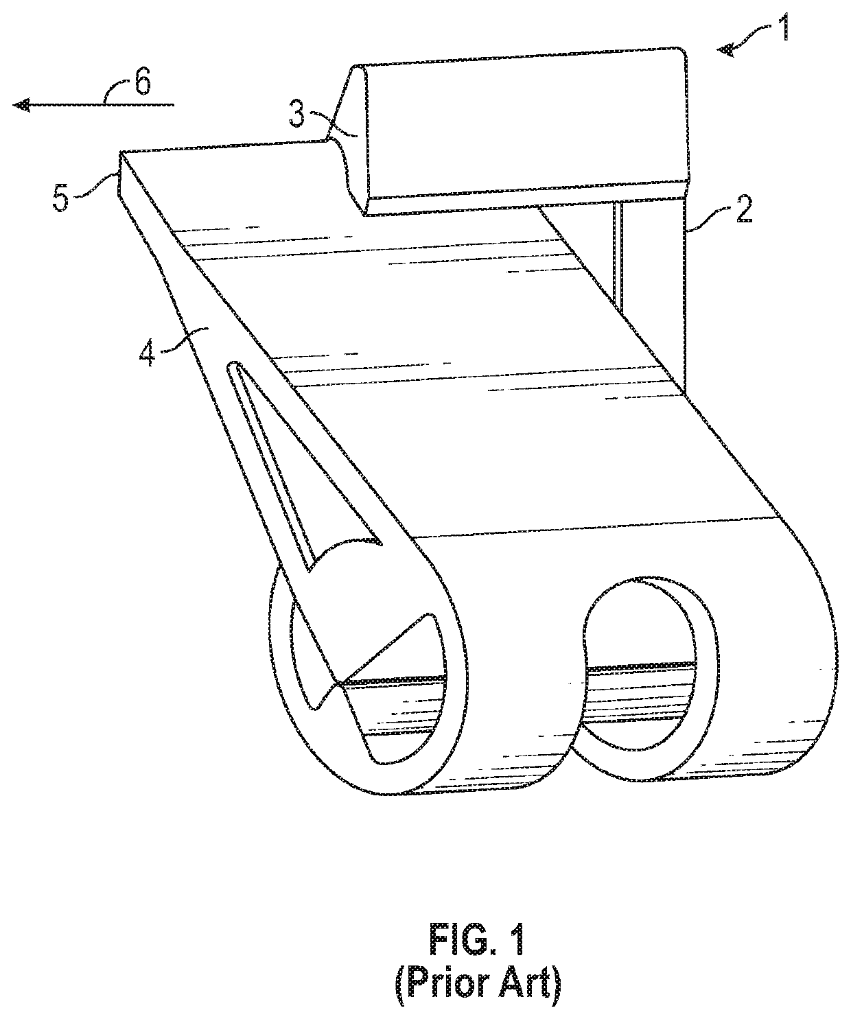
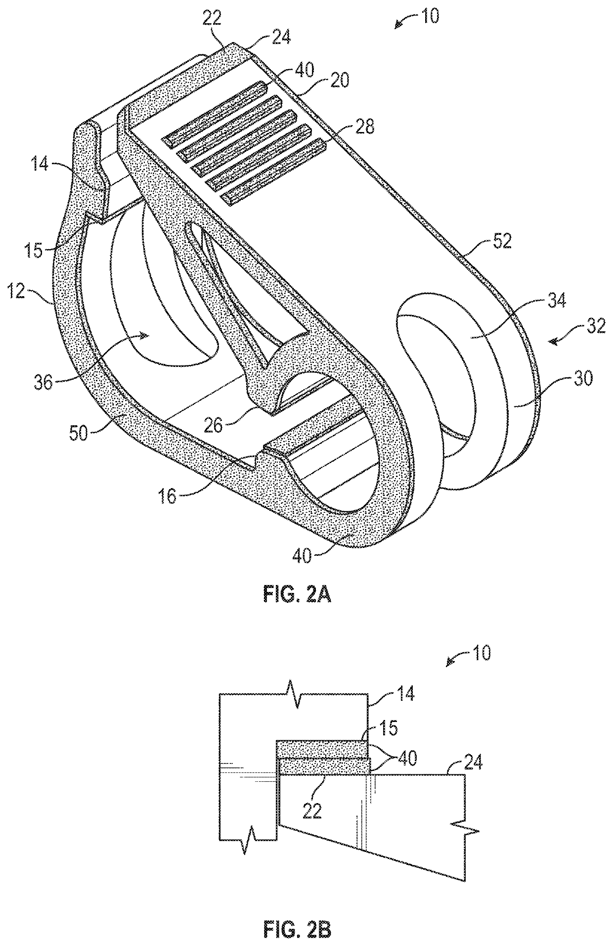
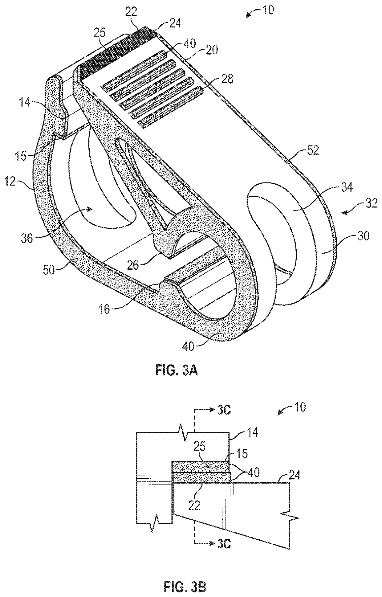
[0042]The present invention relates to pinch-style clamps that are designed for use in clamping or occluding plastic tubing, such as intravenous tubing. The pinch clamp of the present invention addresses and overcomes various difficulties known to exist in prior art pinch clamps. For example, some embodiments of the present invention comprise a soft material applied to various surfaces of the pinch clamp to 1) prevent abrasion or irritation to the patient, 2) increase friction between the pinch clamp and the user operating said pinch clamp, 3) increase friction between engaged surfaces of the pinch clamp to prevent premature or unintended disengagement of the clamp, and 4) increase friction between the outer surfaces of the tubing and the clamping surfaces of the clamp.

[0043]Some embodiments of the present invention further comprise a dynamic clamping surface or interface that results in positive displacement of fluid in the tubing during the process of engaging the pinch clamp. In ...


PUM


Abstract

Pinch-style clamps can be designed for use in clamping or occluding plastic tubing, such as intravenous tubing. These pinch clamps can include a soft, polymer material applied to various surfaces of the pinch clamp to prevent abrasion or irritation to the patient, increase friction between the pinch clamp and the user operating said pinch clamp, increase friction between engaged surfaces of the pinch clamp to prevent premature or unintended disengagement of the clamp, or increase friction between the outer surfaces of the tubing and the clamping surfaces of the clamp. Various features or components can be employed to prevent lateral disengagement of the pinch clamp. A pinch clamp may also be configured with rounded outer edges to enhance patient comfort.

Description

RELATED APPLICATIONS[0001]This application claims the benefit of U.S. Provisional Patent Application No. 62 / 247,615 which was filed on Oct. 28, 2015 and the benefit of U.S. Provisional Patent Application No. 62 / 296,372 which was filed on Feb. 17, 2016.BACKGROUND OF THE INVENTION[0002]The pinch clamp is a well-known type of one-piece plastic clamp which is used to close off plastic tubing, such as intravenous tubing. The pinch clamp generally comprises a smooth, hard plastic material that is resilient and capable of controlled flexion to enable engagement and disengagement of the clamping surfaces.[0003]The molding or extrusion process of manufacturing a pinch clamp generally results in the clamp having sharp edges which may scratch or otherwise irritate the patient with which the clamp is used. Further, the hard, smooth properties of the clamp's plastic create difficulty in grasping and manipulating the clamp during use, especially when the clamp becomes wet.[0004]In some instances,...

Claims


Application Information

Patent Timeline
Patent Type & Authority Patents(United States)
IPC IPC(8): A61M39/28
CPCA61M39/288A61M39/284A61M5/14A61M25/00
Inventor BURKHOLZ, JONATHAN KARLPETERSON, BART D.WANG, BINSTOUT, MARTY L.HU, OLIVIAHARDING, WESTON F.SONDEREGGER, RALPH L.CHAI, KELVINWANG, LIONEL
Owner BECTON DICKINSON & CO
Why Eureka
Try Eureka