Ultra-dense electrode-based brain imaging system

a brain imaging and ultra-dense electrode technology, applied in the field can solve the problems of low localization accuracy, undeveloped ultra-dense electrode arrays at a very large size that can cover a large portion of the whole head, and is not realistic in practical applications, so as to improve the spatial resolution and localization accuracy of reconstructed brain images, enhance sparsity and smoothness, and improve spatial resolution and localization accuracy

Active Publication Date: 2021-06-22
RGT UNIV OF CALIFORNIA
View PDF13 Cites 1 Cited by
  • Summary
  • Abstract
  • Description
  • Claims
  • Application Information

AI Technical Summary

Benefits of technology

[0010]This disclosure describes an ultra-dense electrode-based brain imaging system with high spatial and temporal resolution.
[0011]In one embodiment, an ultra-dense electrode-based brain imaging system may be implemented as a hardware and software system comprising one or more of the following elements: (1) an ultra-dense electrode array, which is able to fully capture functional brain information; (2) spatially focused techniques, resulting in spatially-focused sensing for forward problem analysis; (3) data acquisition architecture with a gigabit wireless transceiver (TX), that is able to support gigabit bandwidth; (4) a realistic head model, constructed from high-resolution MRI; (5) improved brain imaging reconstruction algorithms, which are able to provide brain dynamics with high spatial resolution and localization accuracy; and (6) integrated software and applications, supporting functions such as hardware manipulation, signal recording and processing, and real-time brain state monitoring. Such an imaging system has wide applications varying from exploring the dynamics of human brain (i.e., memory, behavior, etc.) to diagnosis and treatment of brain disorders (i.e., epilepsy, depression, etc.) as well as to personalized learning.
[0012]In one embodiment, the system employs a Sparsity and Smoothness enhanced Method Of Optimized electrical TomograpHy (s-SMOOTH) to improve the spatial resolution and localization accuracy of reconstructed brain images. The method defines a voxel-based Total Generalized Variation (vTGV) regularization on a triangular mesh to enhance high-order smoothness, thus improving the localization accuracy, and utilize l1-2 regularization to enhance sparsity of the image thus improving the spatial resolution. A large variety of experiments on synthetic data with different source configurations and noise levels demonstrated the advantages of this method over state-of-the-art in terms of total reconstruction accuracy, localization accuracy and focalization degree. The tests on event-related potential data further demonstrated the outstanding performance of the method in real scenario. This EEG source imaging method may significantly improve the spatial resolution and localization accuracy for brain image reconstruction, and the method shows the potential of developing new applications that require imaging modality for high temporal and spatial resolution with portable mobility.
[0013]In another embodiment, the system employs a graph Fractional-Order Total Variation (gFOTV) based method to improve the spatial resolution and localization accuracy of reconstructed brain images. The method provides the freedom to choose the smoothness order by imposing sparsity of the spatial fractional derivatives so that it locates source peaks accurately. We compared the performance of gFOTV and various state-of-the-art methods using a large amount of realistic simulations, and evaluated their relative performances with several quantitative criteria. The results demonstrated the superior performance of gFOTV, not only in high spatial resolution but also in high localization accuracy and total reconstruction accuracy.

Problems solved by technology

So far, however, researchers have only tried to use small dense arrays (e.g., less than 64 electrodes) to demonstrate the applications of ultra-dense electrode.
Unfortunately, an ultra-dense electrode array at a very large size that is able to cover a large portion of the whole head has not yet been developed.
There are several technical challenges associated with implementing a large-size ultra-dense electrode array system.
However, TV-based methods assume the source current density is piece-wise constant, i.e., uniform / constant in each sub-region, which is not realistic in practical applications because the source usually has varying intensities.
Consequently this leads to relatively low localization accuracy.
While fMRI is a popular imaging modality since it offers high spatial resolution, its temporal resolution is limited (˜1 s), and is inappropriate to be used in portable applications.

Method used


Image

  • Ultra-dense electrode-based brain imaging system
  • Ultra-dense electrode-based brain imaging system
  • Ultra-dense electrode-based brain imaging system

Examples


Embodiment Construction

[0020]1. Hardware

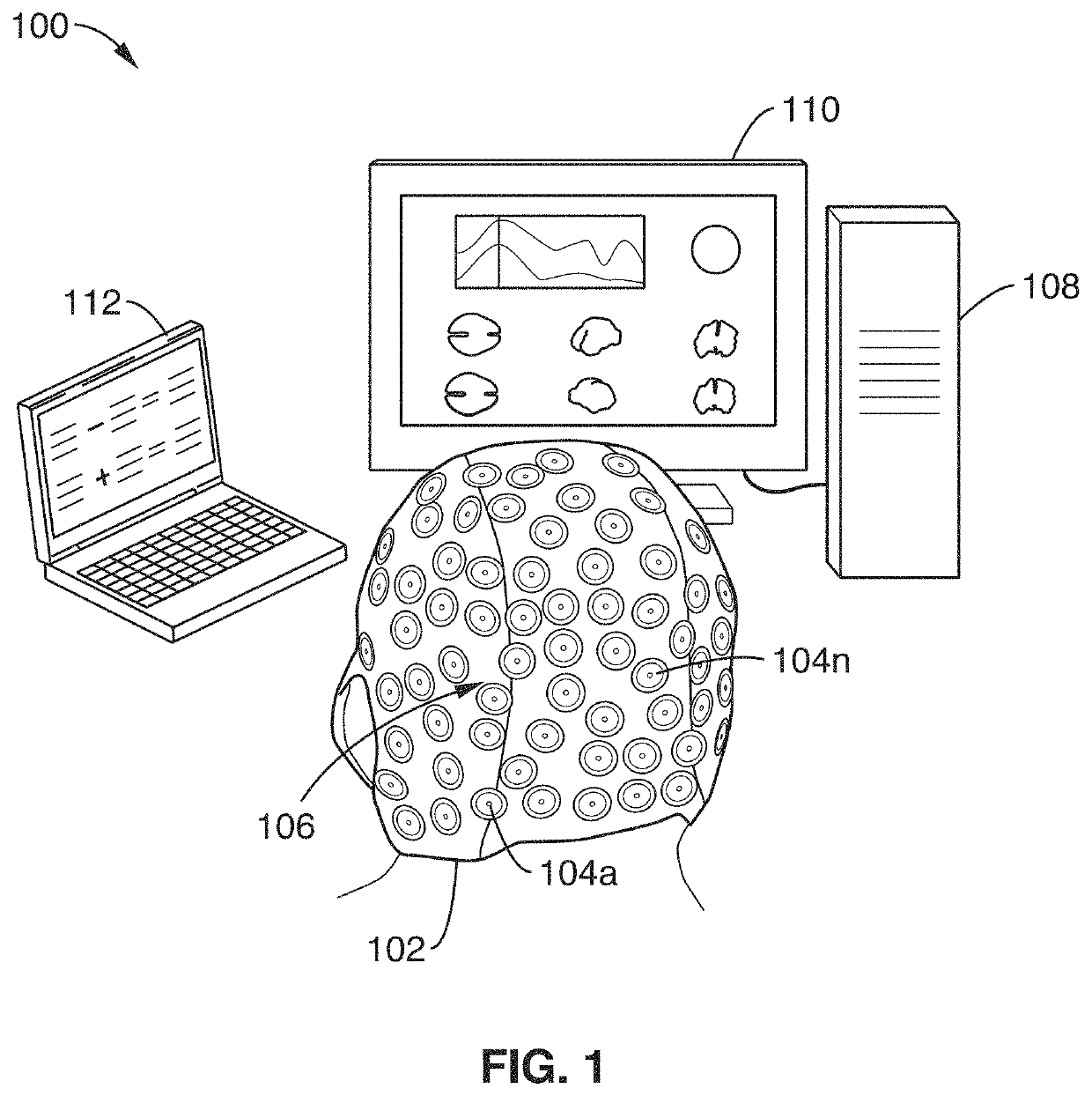
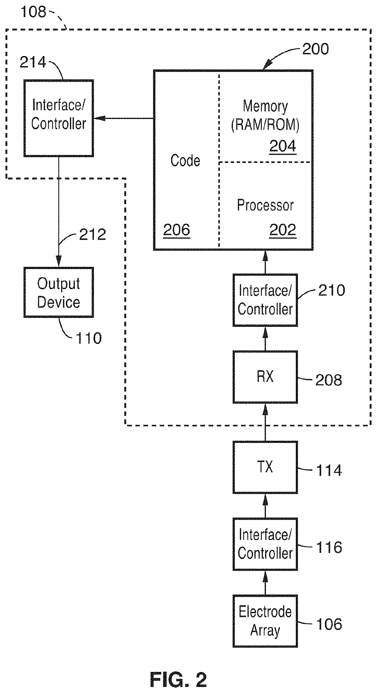
[0021]FIG. 1 and FIG. 2 illustrate the functional components in a generalized embodiment of a brain imaging system according to the technology described herein. It will be appreciated that the embodiment shown may be modified or customized to enable performing the functions described herein.

[0022]As illustrated in FIG. 1, the system 100 includes a head-wearable cap 102 that supports a plurality of electrodes 104a through 104n arranged in a high-density array 106, a data acquisition and processing unit 108 that is configured to receive electrical signals from the electrode array and transform the electrical signals into images, and an output device 110 that is configured to display images generated by the data acquisition and processing unit. Optionally, a visual display 112 or other device can be provided to present visual stimulus to a person wearing the cap. When a visual stimulus is presented, electrical signals are captured by the electrode array in response to ...


PUM


Abstract

An ultra-dense electrode-based brain imaging system with high spatial and temporal resolution. A Sparsity and Smoothness enhanced Method Of Optimized electrical TomograpHy (s-SMOOTH) based reconstruction technique to improve the spatial resolution and localization accuracy of reconstructed brain images is described. Also described is a graph Fractional-Order Total Variation (gFOTV) based reconstruction technique to improve the spatial resolution and localization accuracy of reconstructed brain images.

Description

CROSS-REFERENCE TO RELATED APPLICATIONS[0001]This application is a 35 U.S.C. § 111(a) continuation of PCT international application number PCT / US2016 / 050452 filed on Sep. 6, 2016, incorporated herein by reference in its entirety, which claims priority to, and the benefit of, U.S. provisional patent application Ser. No. 62 / 215,154 filed on Sep. 7, 2015, incorporated herein by reference in its entirety, and which claims priority to, and the benefit of, U.S. provisional patent application Ser. No. 62 / 308,159 filed on Mar. 14, 2016, incorporated herein by reference in its entirety. Priority is claimed to each of the foregoing applications.[0002]The above-referenced PCT international application was published as PCT International Publication No. WO 2017 / 044433 on Mar. 16, 2017, which publication is incorporated herein by reference in its entirety.STATEMENT REGARDING FEDERALLY SPONSORED RESEARCH OR DEVELOPMENT[0003]Not ApplicableINCORPORATION-BY-REFERENCE OF COMPUTER PROGRAM APPENDIX[0004...

Claims


Application Information

Patent Timeline
Patent Type & Authority Patents(United States)
IPC IPC(8): G06T7/00A61B5/291A61B5/316A61B5/374A61B5/378G06T7/246A61B5/00G06T11/00G06T15/08A61B5/055
CPCG06T7/0016A61B5/0006A61B5/291A61B5/316A61B5/374A61B5/378A61B5/721A61B5/743G06T7/248G06T11/005G06T15/08A61B5/055G06T2207/10012G06T2207/10088G06T2207/30016A61B5/7235A61B5/7271A61B5/369A61B5/0042A61B5/0022A61B5/725A61B5/7445A61B2562/0209
Inventor LIU, WENTAILI, YINGQIN, JINGCHANG, CHI-WEILO, YI-KAI
Owner RGT UNIV OF CALIFORNIA
Why Eureka
Try Eureka