

Method and Apparatus for the Generation of EUV Radiation from a Gas Discharge Plasma
- Summary
- Abstract
- Description
- Claims
- Application Information
AI Technical Summary
Benefits of technology
Problems solved by technology
Method used
Image

Examples
first embodiment
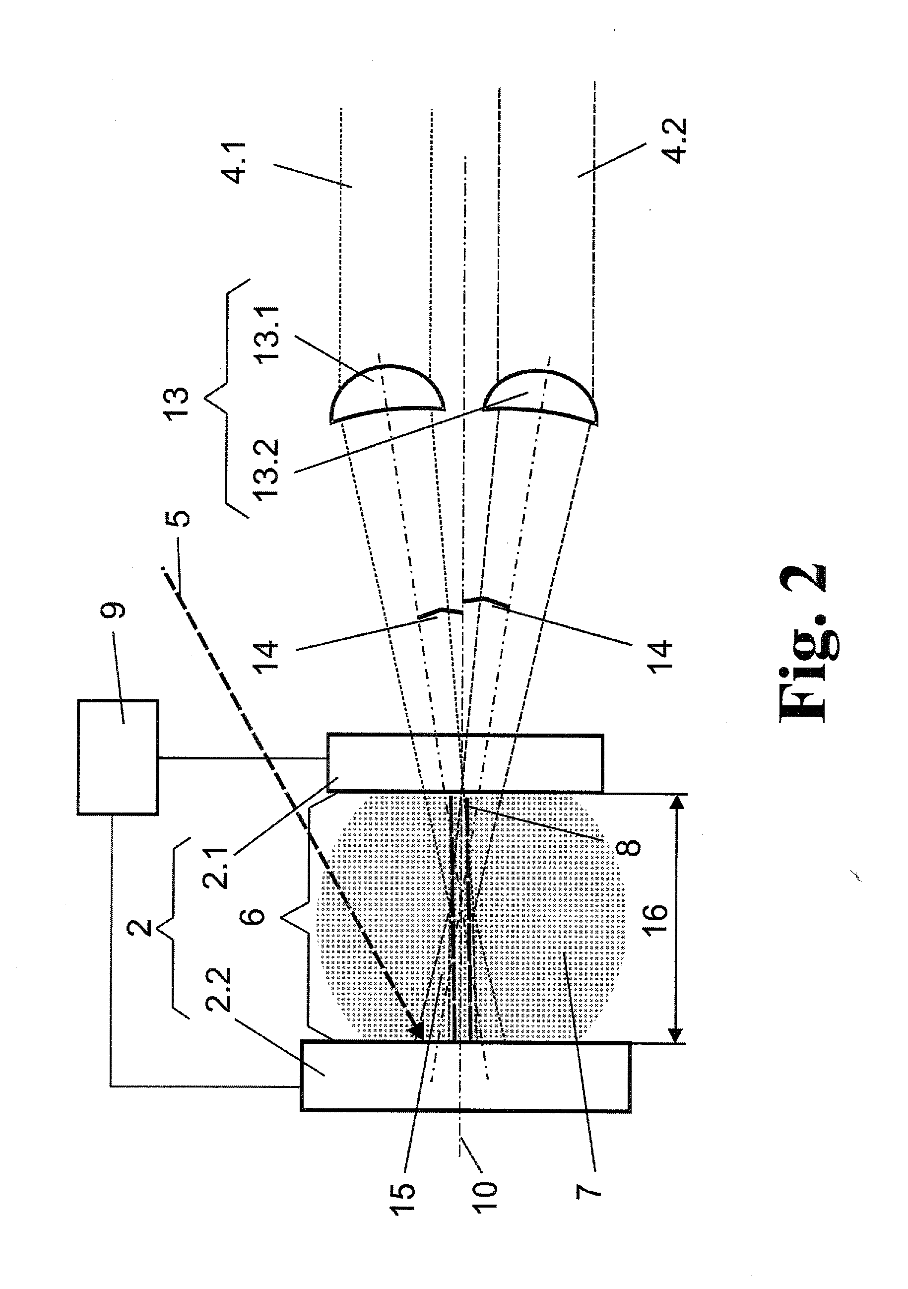
[0054]In the apparatus according to the invention, according to FIG. 2, an anode 2.1 and a cathode 2.2 are provided as disk-shaped electrodes 2 which are oriented parallel to one another and spaced apart from one another. The diameter of the anode 2.1 is smaller than the diameter of the cathode 2.2. A buffer gas 7 is located in a discharge space 6 between the electrodes 2.
[0055]Perpendicular to the surfaces of the electrodes 2, a spacing axis 10 directed from the outside edge of the anode 2.1 to the surface of the cathode 2.2 is defined parallel to an axis of symmetry (not shown) extending through the centers of the electrodes 2. Ideally, the spacing axis 10 should be considered as perpendicular (as the shortest distance line between the electrodes), but can diverge from the perpendicular when the electrode geometry does not permit of radiation along the shortest distance line, or if this is too technically complicated.
[0056]The electrodes 2 communicate with a controlled electric po...
second embodiment
[0067]In the invention, as is shown schematically in FIG. 3, the first partial beam 4.1 and the second partial beam 4.2 are each directed by a line focus 17 into the superposition region 15 which extends along the spacing axis 10 and perpendicular to the incident direction of the partial beams 4.1, 4.2.
[0068]A Nd:YAG laser with adjustable laser pulse durations in the range of 1 ps to 5 ps preferably serves as radiation source 1.1. The beam cross section is expanded by means of a telescope contained in the beam-shaping unit 13 and is formed to a line focus, respectively, and directed into the spacing axis 10 by a cylindrical lens.
[0069]A common line focus 17 is formed along the spacing axis 10 by means of superimposed partial beams 4.1, 4.2. The partial beams 4.1, 4.2 diverge in different directions after the common line focus 17 so that an intensity of the energy beam sufficient for the ionization of the buffer gas 7 (not shown) is reached and a gas breakdown channel is generated on...
PUM
 Abstract
Description
Claims
Application Information