
Photovoltaic system and the manufacturing method thereof

Active Publication Date: 2016-11-10
FLEXWAVE
View PDF5 Cites 4 Cited by
  • Summary
  • Abstract
  • Description
  • Claims
  • Application Information

AI Technical Summary

Benefits of technology

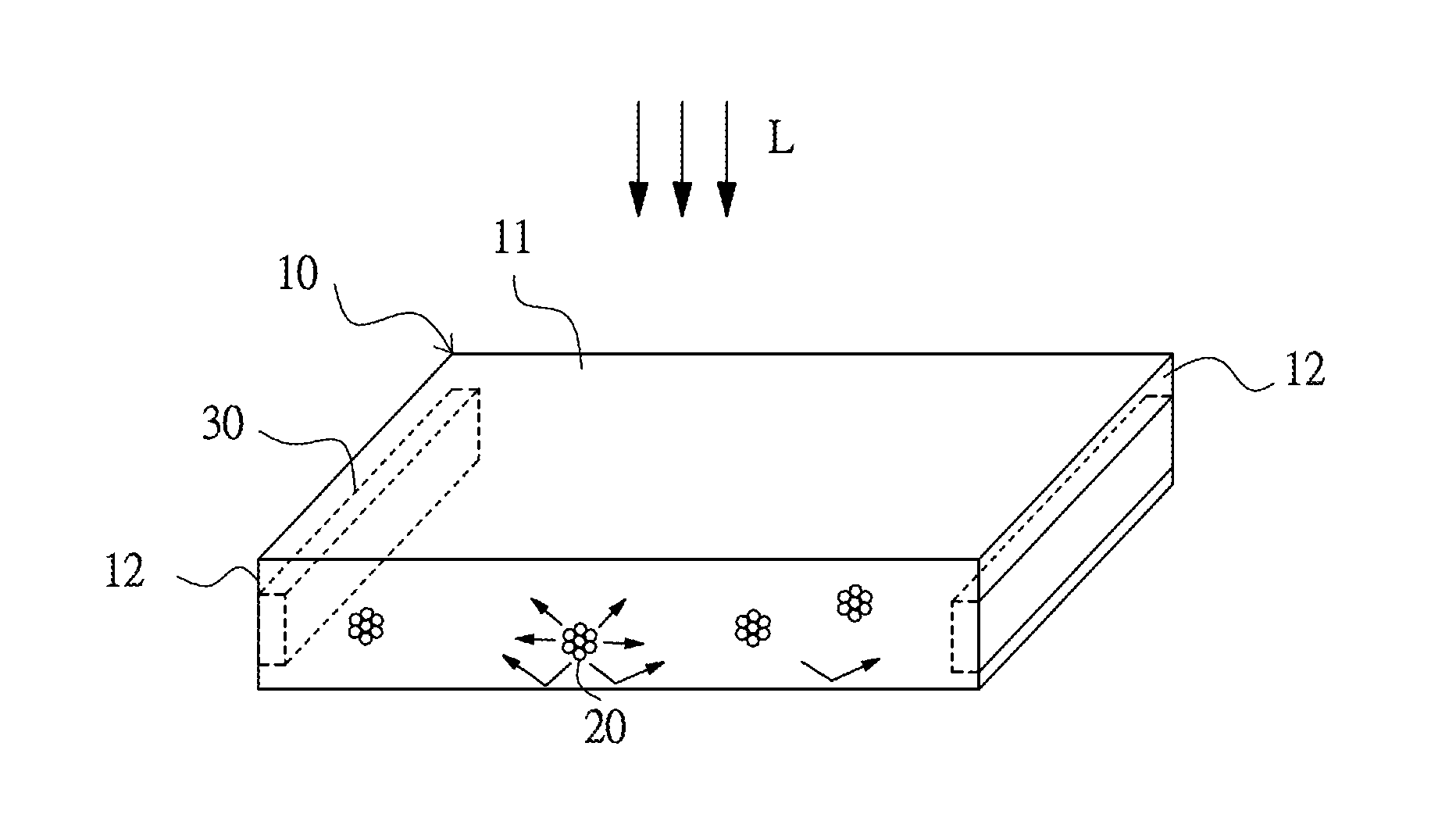
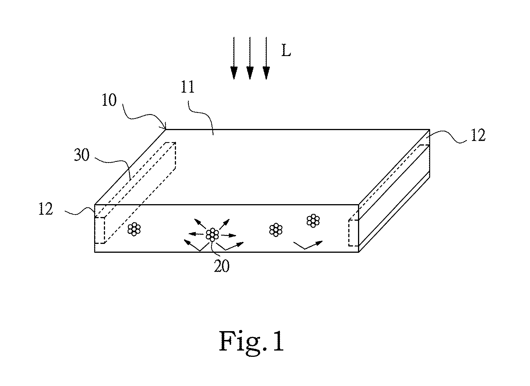
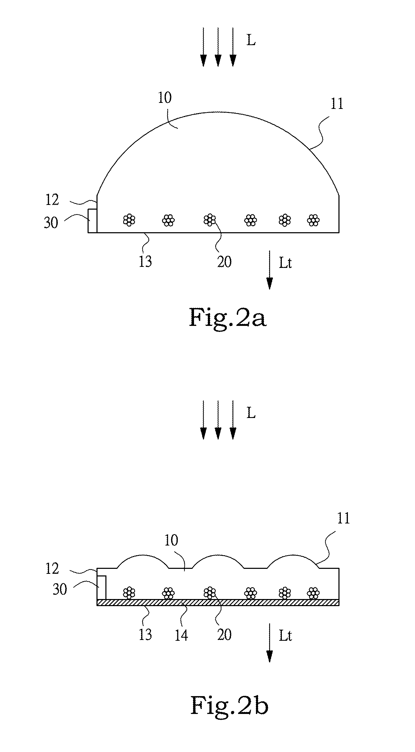
The present invention is about a new photovoltaic system that uses particles made up of a luminescent dye. These particles scatter light in a waveguide, which improves the conversion of sunlight into electricity. The dye also shifts shorter wavelength light into longer wavelengths, which helps to match the ideal working wavelength range of different types of solar cells. This increases the efficiency of the photovoltaic system without needing a scattering layer, which reduces production costs and complexity.

Problems solved by technology

As a result, the production cost and the complexity of the elements of the photovoltaic system are relatively increased.

Method used


Image

  • Photovoltaic system and the manufacturing method thereof
  • Photovoltaic system and the manufacturing method thereof
  • Photovoltaic system and the manufacturing method thereof

Examples


Embodiment Construction

[0021]Various embodiments of the present invention will be described in detail below and illustrated in conjunction with the accompanying drawings. In addition to these detailed descriptions, the present invention can be widely implemented in other embodiments, and apparent alternations, modifications and equivalent changes of any mentioned embodiments are all included within the scope of the present invention and based on the scope of the Claims. In the descriptions of the specification, in order to make readers have a more complete understanding about the present invention, many specific details are provided; however, the present invention may be implemented without parts or all of the specific details. In addition, the well-known steps or elements are not described in detail, in order to avoid unnecessary limitations to the present invention. Same or similar elements in Figures will be indicated by same or similar reference numbers. It is noted that the Figures are schematic and ...


PUM


Abstract

A photovoltaic system consists of a waveguide body, luminescent dyes and a photovoltaic cell. Luminescent dyes and their aggregated particulates with larger diameter are dispersed in the waveguide body to scatter light and transform the first light of the external light into a second light, wherein the wavelength of the second light is longer than the wavelength of the first light. Compared to conventional techniques, the use of luminescent dyes of the present invention can be aggregated into particulates with larger diameter to enhance the power conversion efficiency of the photovoltaic cell, without providing a scattering layer, in order to reduce the production cost and the element complexity of the photovoltaic system. A manufacturing method for a photovoltaic system is also disclosed.

Description

BACKGROUND OF THE INVENTION[0001]1. Field of the Invention[0002]The present invention relates to a power system and a manufacturing method thereof, and particularly to a photovoltaic system and a manufacturing method thereof.[0003]2. Description of the Prior Art[0004]A traditional photovoltaic system comprises an optical waveguide element composed of glass to guide sunlight to irradiate on a photovoltaic cell, so as to generate electricity. However, in order to increase power efficiency, it is usually needed to dispose a reflection board or scattering structure on a surface of the optical waveguide element, such that the photovoltaic cell can absorb more sunlight. As a result, the production cost and the complexity of the elements of the photovoltaic system are relatively increased.[0005]To sum up the foregoing descriptions, how to provide a photovoltaic system, which can enhance the power efficiency easily, and a manufacturing method thereof is the most important goal for now.SUMMA...

Claims


Application Information

Patent Timeline
IPC IPC(8): H01L31/055H01L31/18H01L31/0232
CPCH01L31/055H01L31/18H01L31/02327H01L31/0547Y02E10/52
Inventor CHOU, CHUN-HSIENHSU, MIN-HUNGKAN, CHIA-CHI
Owner FLEXWAVE
Learn More