
Switching converter for lighting with light intensity as feedback and light emitting apparatus using the same

Active Publication Date: 2010-04-22
CAPELLA MICROSYSTEMS (TAIWAN) INC
View PDF5 Cites 10 Cited by
  • Summary
  • Abstract
  • Description
  • Claims
  • Application Information

AI Technical Summary

Benefits of technology

[0006]Therefore, one of objects of the present invention is to provide a switching converter with light intensity as feedback and a light emitting apparatus using the same, so as to enhance the power efficiency of the light emitting apparatus and avoid unnecessary power consumption by the apparatus.
[0007]Another object of the present invention is to provide a switching converter with light intensity as feedback and a light emitting apparatus using the same, so as to extend the service life of the light emitting element.
[0008]Another object of the present invention is to provide a switching converter with light intensity as feedback and a light emitting apparatus using the same, so that the light emitting element can have accurately controlled luminous intensity.

Problems solved by technology

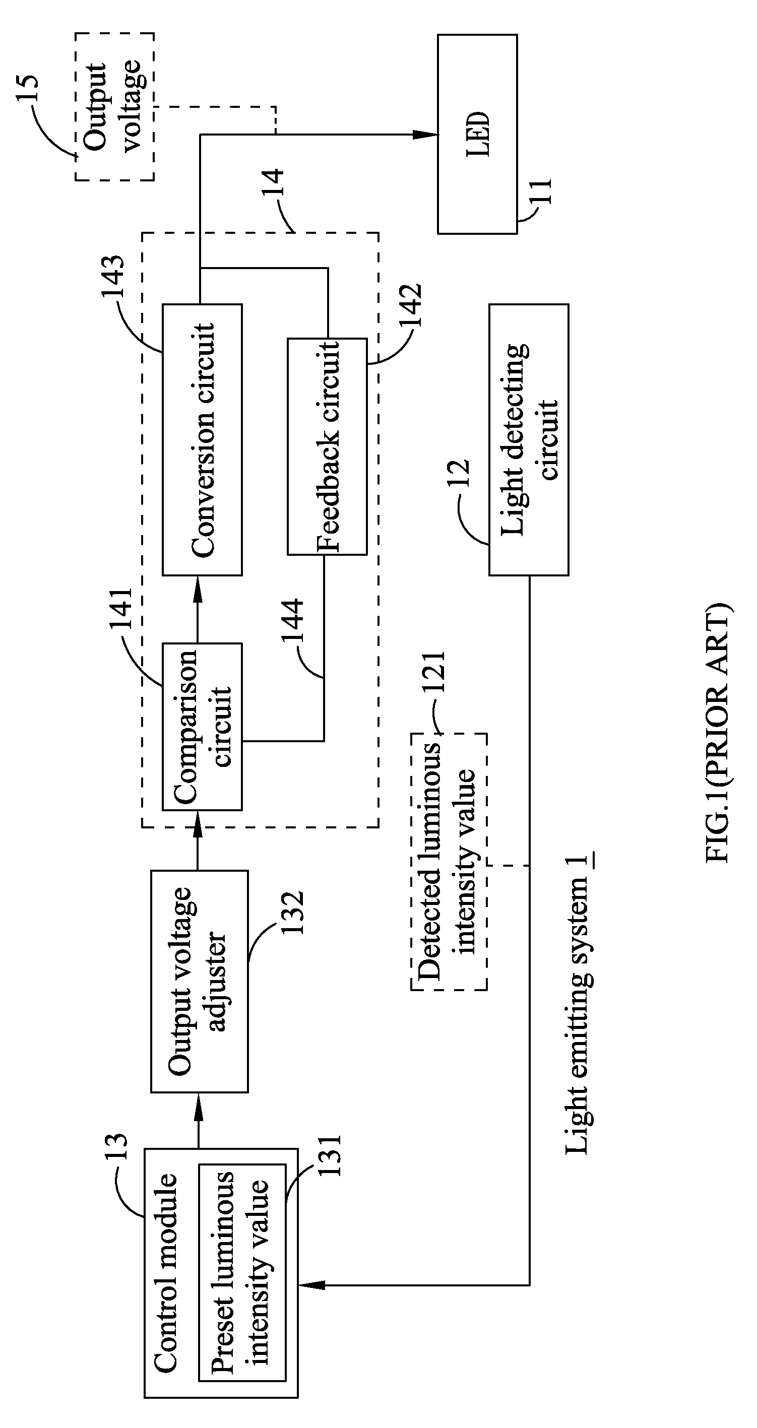
Therefore, the circuitry design for the light emitting system 1 in prior art has the disadvantages of having low power efficiency and consuming unnecessary power.

Method used


Image

  • Switching converter for lighting with light intensity as feedback and light emitting apparatus using the same
  • Switching converter for lighting with light intensity as feedback and light emitting apparatus using the same
  • Switching converter for lighting with light intensity as feedback and light emitting apparatus using the same

Examples


first embodiment

[0039]FIG. 3 illustrates a schematic view of a light emitting apparatus according to the present invention. The light emitting apparatus 3 comprises a light emitting diode module 31 and a voltage converter 32. The light emitting diode module 31 comprises a plurality of light emitting diodes 311. In the illustrated embodiment, the light emitting diodes 311 are connected in series. However, the light emitting diodes 311 can be otherwise connected in parallel according to actual need. The light emitting diode module 31 receives a driving voltage 321 output by the voltage converter 32 and the light emitting diodes 311 are then driven to emit light beams 312.

[0040]The voltage converter 32 comprises a microcontroller 33, a pulse width modulation (PWM) signal generating circuit 341, a transistor 342, a diode 343, a silicon photodiode 351 and a light detecting circuit 353. One terminal of the silicon photodiode is connected with an input voltage, and another terminal is connected to the lig...

second embodiment

[0042]FIG. 4 illustrates a schematic view of a light emitting apparatus according to the present invention. The light emitting apparatus 4 comprises a plurality of serially connected red light emitting diodes (LEDs) 411, a plurality of serially connected green LEDs 412, a plurality of blue LEDs 413, a plurality of comparators 421˜424, a plurality of transistors 431˜434, an adder 44, a plurality of silicon photodiodes 451˜453, a plurality of diodes 471˜473, and a time slot controller 47.

[0043]The comparator 424, the transistor 434, and the diodes 471˜473 are used to control the luminous intensity of the light emitting apparatus 4, and the time slot controller 47 and the transistors 431˜433 are used to control the ratio of red light, green light, and blue light to one another in order to adjust the light colors or color temperatures of the light emitting apparatus 4. The silicon photodiodes 451˜453 are respectively provided with a red filter, a green filter, and a blue filter for dete...


PUM


Abstract

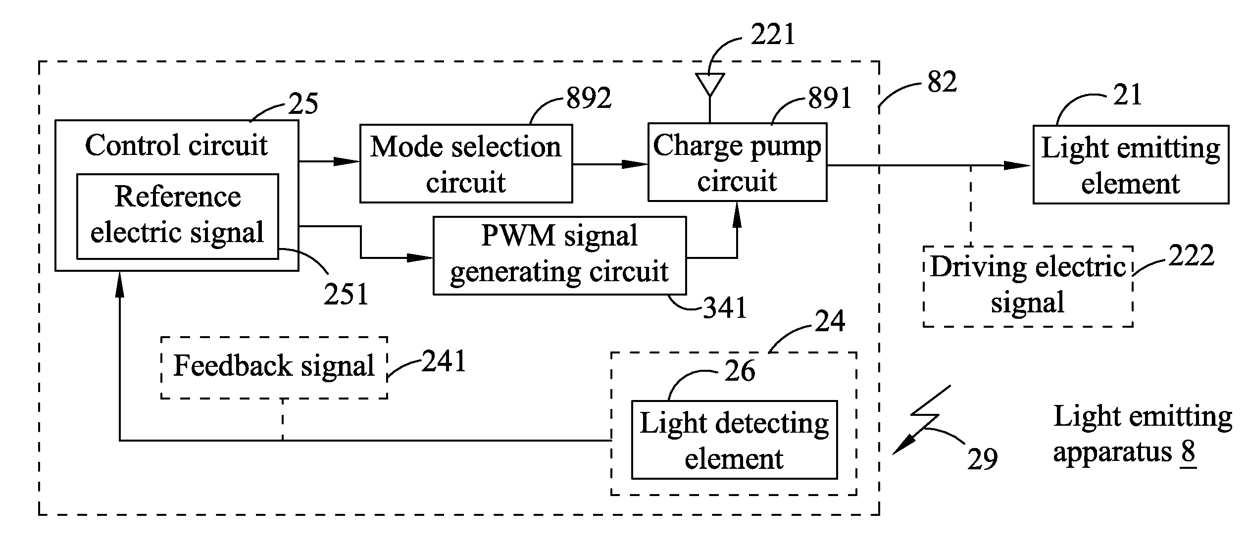
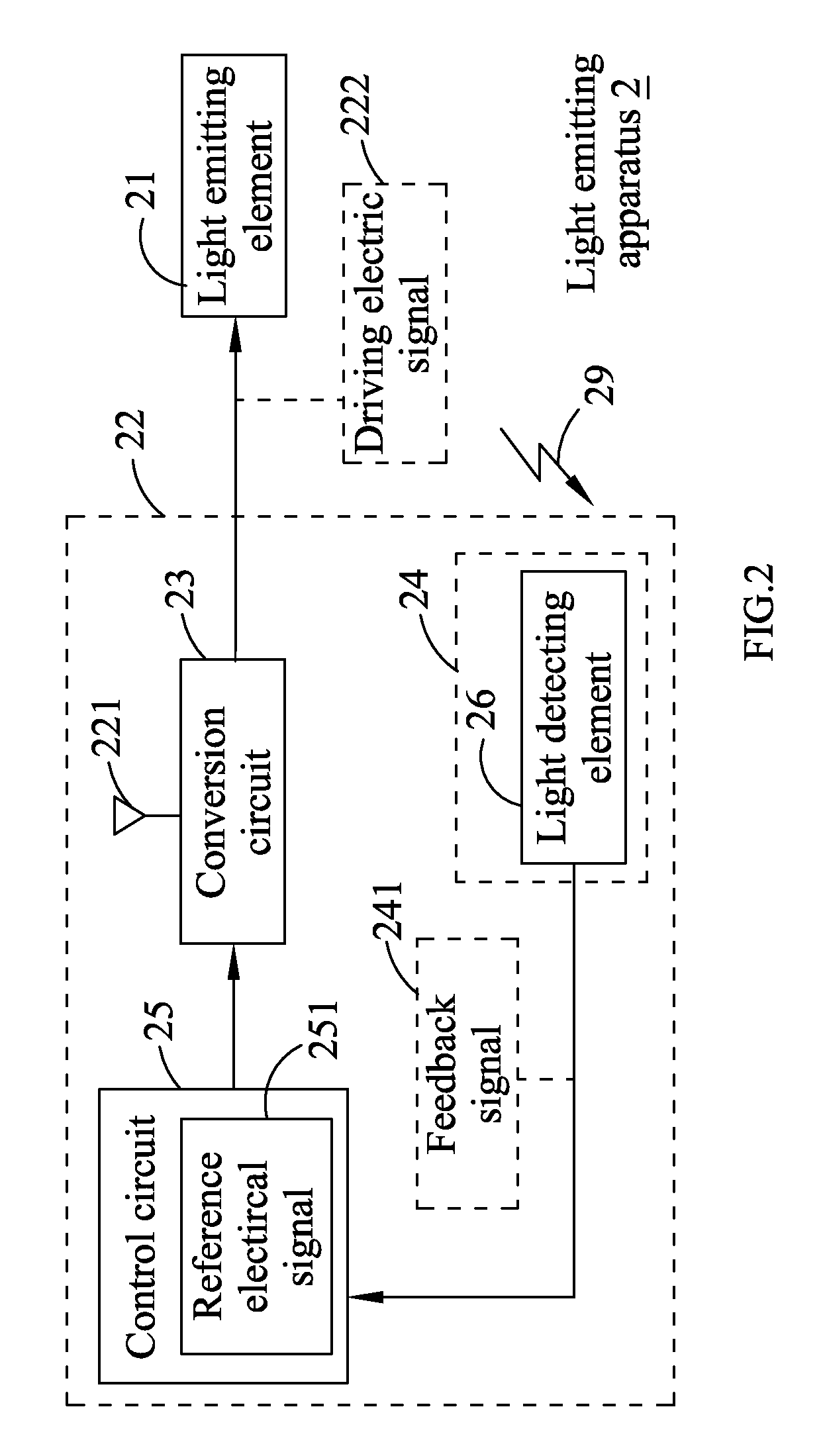
A light emitting apparatus comprises a light emitting element and a switching converter comprising a conversion circuit for converting an operating electric signal to generate the driving electric signal, a feedback circuit having a light detecting element for detecting a luminous intensity of the light emitting element and generating a feedback signal, and a control circuit for receiving the feedback signal, comparing the received feedback signal with a reference electric signal, and controlling the conversion circuit based on comparison results to adjust the driving electric signal. Alternatively, the light detecting element detects ambient light and the control circuit controls the conversion circuit based on comparison results to stop or enable outputting of the driving electric signal.

Description

FIELD OF THE INVENTION[0001]The present invention relates to a switching converter for lighting, and more particularly to a high efficient switching converter capable of receiving light intensity as feedback, and to a light emitting apparatus using such high efficient switch converter.BACKGROUND OF THE INVENTION[0002]Most prior art light emitting systems using light emitting diodes (LEDs) would include a light detecting circuit. One of the purposes of using the light detecting circuit is to stabilize the luminous intensity of the light emitting system. The light detecting circuit is used for detecting the luminous intensity of the light emitting system, and the detected luminous intensity is then compared with a preset luminous intensity, and the driving voltage of the LEDs is adjusted based on comparison results, so that the luminous intensity of the light emitting system can be maintained at the preset luminous intensity. The driving voltage is generated by a voltage converter mod...

Claims


Application Information

Patent Timeline
IPC IPC(8): H05B37/02
CPCH05B33/0854H05B33/0851H05B45/12
Inventor LIN, YUH-MINSHIH, CHENG-CHUNG
Owner CAPELLA MICROSYSTEMS (TAIWAN) INC
Learn More