Optical proximity correction methodology using pattern classification for target placement

a pattern classification and optical proximity technology, applied in the field of optical proximity correction (opc) techniques, can solve the problems of not being entirely satisfactory in all, and the design of the integrated circuit becomes more challenging

Active Publication Date: 2021-06-29
TAIWAN SEMICON MFG CO LTD
View PDF31 Cites 0 Cited by
  • Summary
  • Abstract
  • Description
  • Claims
  • Application Information

AI Technical Summary

Problems solved by technology

Integrated circuit (IC) design becomes more challenging as IC technologies continually progress towards smaller feature sizes, such as 32 nanometers, 28 nanometers, 20 nanometers, and below.
Although such methods have been generally adequate for their intended purposes, they have not been entirely satisfactory in all respects

Method used


Image

  • Optical proximity correction methodology using pattern classification for target placement
  • Optical proximity correction methodology using pattern classification for target placement
  • Optical proximity correction methodology using pattern classification for target placement

Examples


Embodiment Construction

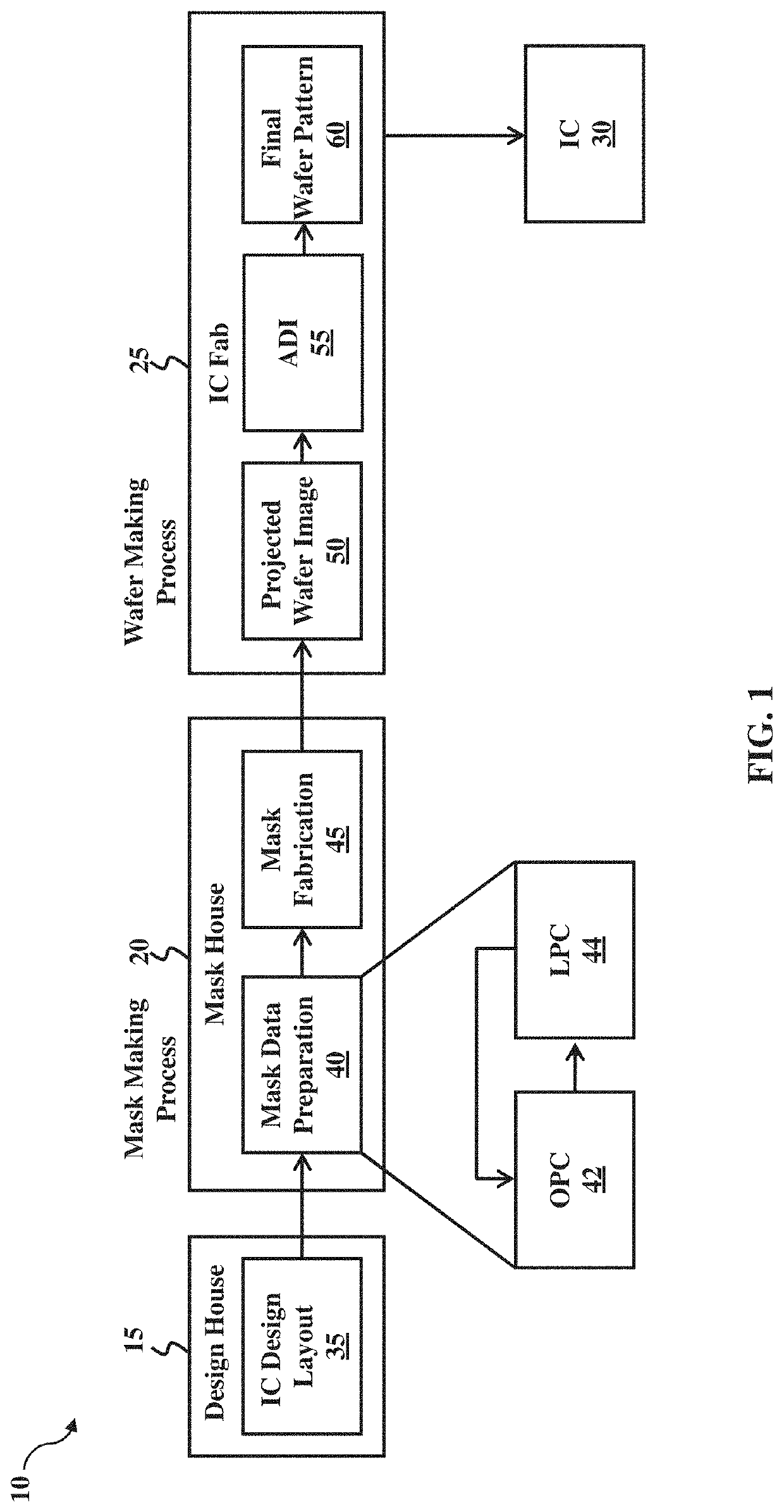
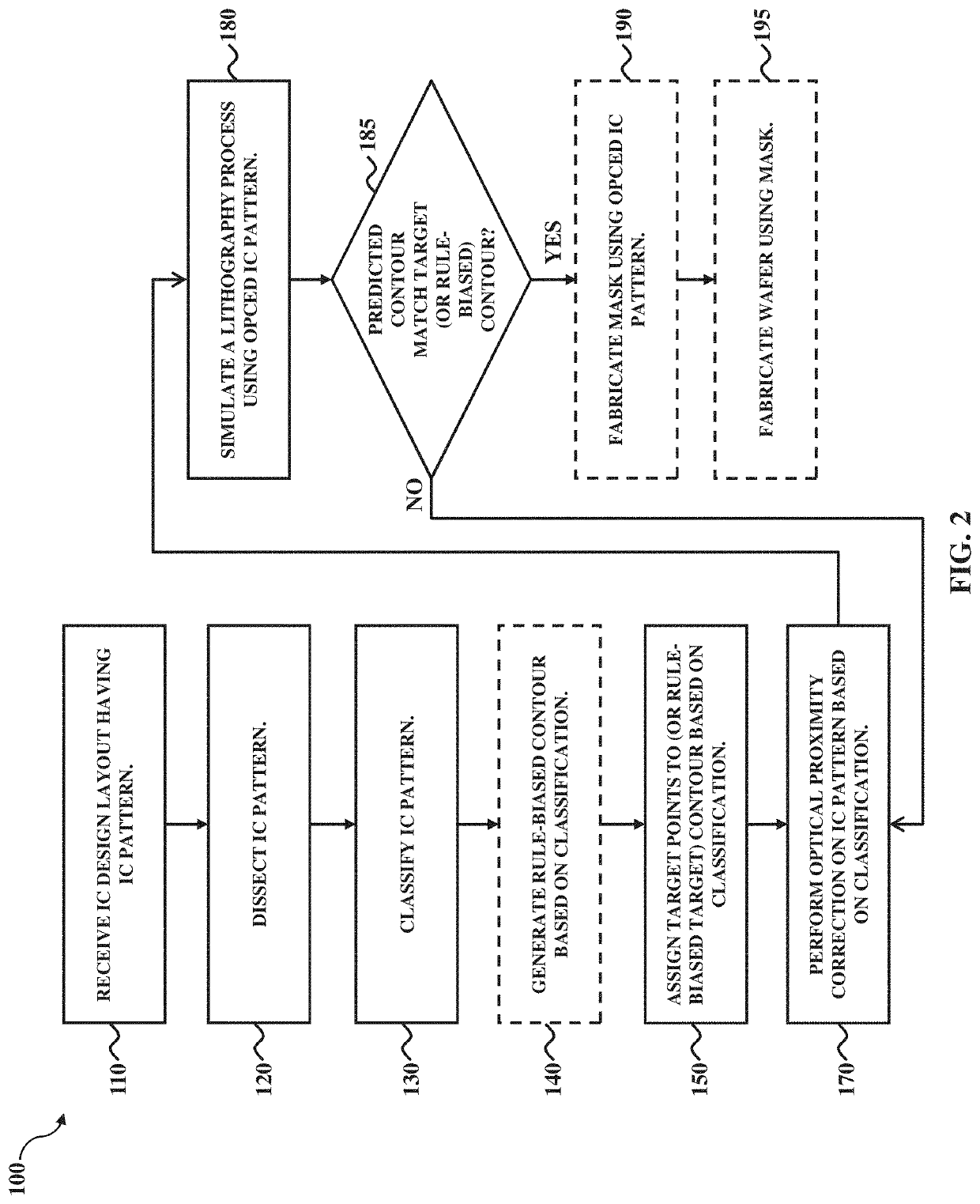
[0012]The present disclosure relates generally to lithography optimization techniques, and more particularly, to optical proximity correction (OPC) techniques.

[0013]The following disclosure provides many different embodiments, or examples, for implementing different features of the invention. Specific examples of components and arrangements are described below to simplify the present disclosure. These are, of course, merely examples and are not intended to be limiting. For example, the formation of a first feature over or on a second feature in the description that follows may include embodiments in which the first and second features are formed in direct contact, and may also include embodiments in which additional features may be formed between the first and second features, such that the first and second features may not be in direct contact. In addition, the present disclosure may repeat reference numerals and / or letters in the various examples. This repetition is for the purpos...


PUM

PropertyMeasurementUnit
sizesaaaaaaaaaa
sizesaaaaaaaaaa
sizesaaaaaaaaaa

Abstract

Optical proximity correction (OPC) based computational lithography techniques are disclosed herein for enhancing lithography printability. An exemplary mask optimization method includes receiving an integrated circuit (IC) design layout having an IC pattern; generating target points for a contour corresponding with the IC pattern based on a target placement model, wherein the target placement model is selected based on a classification of the IC pattern; and performing an OPC on the IC pattern using the target points, thereby generating a modified IC design layout. The method can further include fabricating a mask based on the modified IC design layout. The OPC can select an OPC model based on the classification of the IC pattern. The OPC model can weight the target placement model.

Description

PRIORITY DATA[0001]This application is a continuation application of U.S. patent application Ser. No. 15 / 653,784, filed Jul. 19, 2017, which is a non-provisional application of claims the benefit of U.S. Provisional Patent Application Ser. No. 62 / 436,877, filed Dec. 20, 2016, each of which is herein incorporated by reference in its entirety.BACKGROUND[0002]Integrated circuit (IC) design becomes more challenging as IC technologies continually progress towards smaller feature sizes, such as 32 nanometers, 28 nanometers, 20 nanometers, and below. For example, when fabricating IC devices, IC device performance is seriously influenced by lithography printability capability, which indicates how well a final wafer pattern formed on a wafer corresponds with a target pattern defined by an IC design layout. Various methods that focus on optimizing a mask used for projecting an image that corresponds with the target pattern on the wafer have been introduced for enhancing lithography printabili...

Claims


Application Information

Patent Timeline
Patent Type & Authority Patents(United States)
IPC IPC(8): G03F1/36G06F30/398
CPCG03F1/36G06F30/398G06F30/392
Inventor WANG, HUNG-CHUNLIU, CHI-PINGCHANG, FENG-JUCHANG, CHING-HSULIU, WEN HAOYEH, CHIA-FENGCHIH, MING-HUITSAI, CHENG KUNCHIEN, WEI-CHENHUANG, WEN-CHUNTANG, YU-PO
Owner TAIWAN SEMICON MFG CO LTD
Why Eureka
Try Eureka