Method and system for load alleviation

a technology of load alleviation and load, applied in process and machine control, non-electric variable control, instruments, etc., can solve the problems of large load changes, difficult movement of large aircraft parts from one station to another, and many complex processes for aircraft manufacturing, so as to prevent damage to objects and reduce load

Active Publication Date: 2021-07-06
THE BOEING CO
View PDF6 Cites 0 Cited by
  • Summary
  • Abstract
  • Description
  • Claims
  • Application Information

AI Technical Summary

Benefits of technology

[0007]An illustrative embodiment of the present disclosure provides a method for alleviating a load. A support system is positioned at a nominal location with respect to an object. The support system comprises jacks and supports. Each of the supports is associated with one of the jacks. The object is positioned on the support system. The support system with the object is moved across a path. The height of each of the jacks is adjusted as the support system moves along the path to maintain a desired load on each jack. Maintaining the desired load prevents damage to the object.
[0009]A further illustrative embodiment of the present disclosure provides a method for alleviating a load. An aircraft structure is positioned on a support system. The support system comprises a plurality of tools. Each tool has a hydraulic jack, a support associated with the hydraulic jack, and a movement system. The support system with the aircraft structure is moved across a path. A height of the plurality of tools is adjusted as the support system moves along the path to maintain a desired load on each tool. Maintaining the desired load prevents damage to the object.

Problems solved by technology

Manufacturing of an aircraft requires many complex processes.
Movement of large aircraft parts from one station to another may be difficult due to their size, shape, and complexity.
Even small vertical movements by the supports result in large load changes.
As the supports move about the manufacturing facility, uneven flooring may result in unexpected vertical movement of the tooling support points.
These large load changes may result in damage to the tool, the aircraft part, or both.
Further, these load changes may possibly affect the quality and integrity of the part.

Method used


Image

  • Method and system for load alleviation
  • Method and system for load alleviation
  • Method and system for load alleviation

Examples


Embodiment Construction

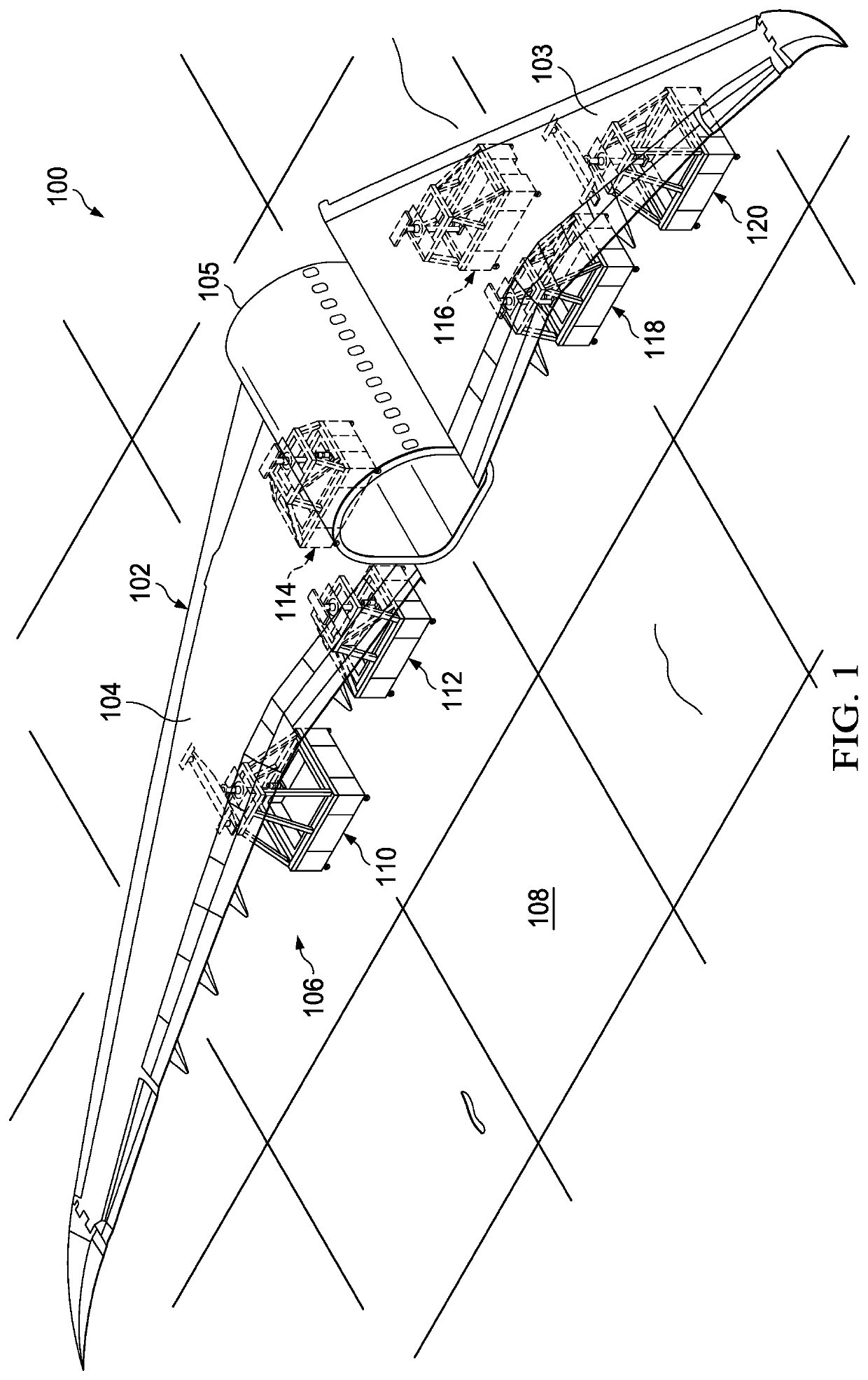
[0021]The illustrative embodiments recognize and take into account one or more different considerations. For example, the illustrative embodiments recognize and take into account that the manufacturing process for an aircraft includes moving large, fragile parts from one location to another location in the manufacturing environment. As the parts are moved over uneven flooring, changes in height of one or more support points under the part may increase or decrease vertical loads. In some cases, a point may be overloaded, risking damage to the part or supporting tooling.

[0022]The illustrative embodiments also recognize and take into account that some currently employed solutions are more complex or use more resources than desired. As an example, active load alleviation may be used to avoid overload at tooling support points. Active load alleviation may require vertical screws to adjust in response to feedback from load cells at the tooling support points. In such a system, a servo mot...


PUM


Abstract

A method and system for alleviating a load is provided. A support system is positioned at a nominal location with respect to an object. The support system comprises jacks and supports. Each of the supports is associated with one of the jacks. The object is positioned on the support system. The support system with the object is moved across a path. The height of each of the jacks is adjusted as the support system moves along the path to maintain a desired minimum load on each jack. Maintaining the desired minimum load prevents damage to the object.

Description

RELATED PROVISIONAL APPLICATION[0001]This application claims the benefit of U.S. Provisional Patent Application Ser. No. 62 / 660,236, filed Apr. 19, 2018, and entitled “Method and System for Load Alleviation.”BACKGROUND INFORMATION1. Field[0002]The present disclosure relates generally to manufacturing processes for aircraft applications. More specifically, the present disclosure relates to a method and system for load alleviation that prevents damage to an aircraft structure and associated tooling as the aircraft structure moves about the manufacturing facility.2. Background[0003]Manufacturing of an aircraft requires many complex processes. Aircraft parts may be moved from one location to another as they are formed and assembled. Movement of large aircraft parts from one station to another may be difficult due to their size, shape, and complexity.[0004]Manufacturers often use portable tools to transport and support an aircraft part as it moves about the manufacturing facility. For ex...

Claims


Application Information

Patent Timeline
Patent Type & Authority Patents(United States)
IPC IPC(8): B64F5/50B66F5/04G05D27/02G05D1/02
CPCB64F5/50B66F5/04G05D1/0212G05D27/02G05D2201/0216G05D1/0293
Inventor MERRIT, BENJAMIN SAMUELSTONE, PATRICK B.RUSSELL, DON J.DUNLAP, BRENNAN JOHN
Owner THE BOEING CO
Why Eureka
Try Eureka