Touch sensor circuit and touch sensor method

a touch sensor and touch sensor technology, applied in the field of touch sensing, can solve the problems of inability to implement multi-touch sensing, easy to affect multi-capacitive touch sensing, wrong or inaccurate detection, etc., to achieve shorten the duration of touch sensing, enhance multi-capacitive sensing accuracy, and reduce environmental affection

Active Publication Date: 2021-07-06
SILICON INTEGRATED SYSTEMS
View PDF5 Cites 0 Cited by
  • Summary
  • Abstract
  • Description
  • Claims
  • Application Information

AI Technical Summary

Benefits of technology

[0008]By utilizing the sensor circuit and sensor method of the present disclosure, self-capacitive touch sensing implements during charging to the mutual-capacitive sensor circuit, thus self-capacitive touch sensing and mutual-capacitive touch sensing can implement at the same time. So that the accuracy of multi-touch sensing is enhanced and the environmental affection is reduced. The duration of touch sensing is shorten and the efficiency of touch sensing are improved.

Problems solved by technology

However, mutual-capacitive touch sensing is easily affected by environment, such as wet fingers of users, humidity or temperature of atmosphere, drop or spot on screen, etc.
These environmental affections cause wrong or inaccurate detection results.
In contrast, self-capacitive touch sensing is hardly affected by environment but cannot implement multi-touch sensing.
The operation efficiency may be affected and become slower.

Method used


Image

  • Touch sensor circuit and touch sensor method
  • Touch sensor circuit and touch sensor method
  • Touch sensor circuit and touch sensor method

Examples


first embodiment

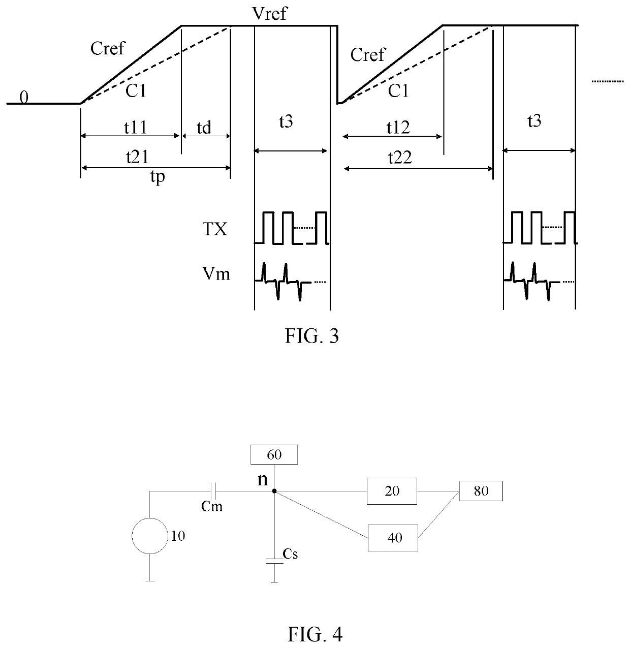
[0020]Please refer to FIG. 3 which illustrates a second kind of time sequence of the The difference of the second kind of time sequence from the first kind of time sequence is what is measured in the second kind of time sequence is the time tp required for the first capacitor Cs charge to the level as reference voltage Vref. Then comparing time tp with time t11 for a reference capacitor charge to the level as reference voltage Vref to determine whether touch is happened on the point corresponding to the first capacitor Cs or not. When the voltage of node n reaches a work voltage of the mutual-capacitive sensor circuit, the mutual-capacitive touch detection is performed.

[0021]The detail steps in the second kind of time sequence of the first embodiment of the present disclosure are as follows. Charge the node n between the mutual-capacitive sensor circuit 20 and the self-capacitive sensor circuit 40. Detecting duration of time t21 which represents time required for charging voltage o...

second embodiment

[0025]It should be noticed that the charging unit 60 can be isolated from touch sensor circuit as shown in FIG. 4 which illustrates the

third embodiment

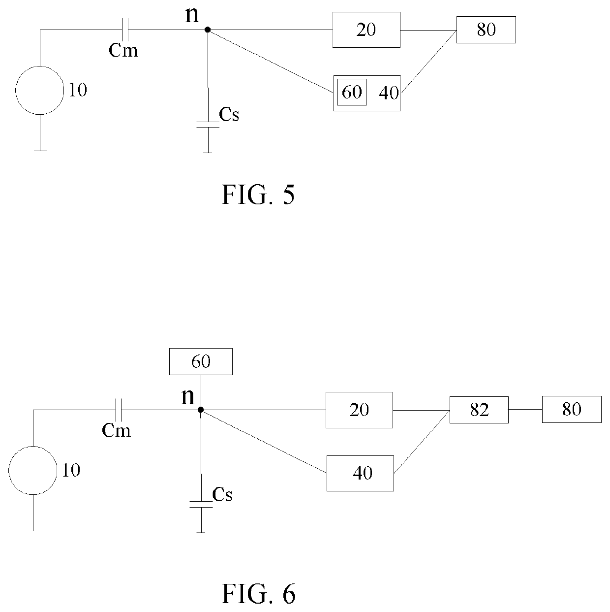
[0026]FIG. 5 illustrates the present disclosure. As shown in FIG. 5, the charging unit 60 can also be disposed in the mutual-capacitive sensor circuit 40. Thus, additional space for disposing isolated the charging unit 60 can be saved.

[0027]In the second the third embodiments, the charge unit can independently charge the mutual-capacitive sensor circuit 20 so that the implement of the mutual-capacitive sensor circuit 20 will not be affected by the voltage of the first capacitor Cs in the self-capacitive sensor circuit 40. As a result, even the voltage Vs in period is becomes lower due to touch happens on the first capacitor Cs, the mutual-capacitive sensor circuit 20 still work normally because the voltage of node n will be charged to work voltage by the charging unit 60.

[0028]Please refer to FIG. 6 which illustrates the fourth embodiment of the present disclosure. A touch sensor circuit 1 of the fourth embodiment includes a driving circuit 10, a mutual-capacitive sensor circuit 20,...


PUM


Abstract

A circuit for touch sensing includes a driving unit, a self-capacitive sensor circuit, a mutual-capacitive sensor circuit and a control circuit. The driving is configured to generate a driving signal. The self-capacitive sensor circuit is configured to generate a self-capacitance sensing result. The mutual-capacitive sensor circuit is configured to receive the driving signal in order to generate a mutual-capacitance sensing result when the voltage of a node between the self-capacitive sensor circuit and the mutual-capacitive sensor circuit reaches a reference voltage. The control circuit receives and computes the self-capacitance sensing result and the mutual-capacitance sensing result in order to generate a sensing result. By utilizing the circuit for touch sensing of present disclosure, the accuracy and the efficiency of touch sensing can be enhanced.

Description

FIELD OF INVENTION[0001]The present disclosure relates to a method for touch sensing and, more particularly, to a touch sensing method for implementing mutual-capacitive and self-capacitive sensing at the same time.BACKGROUND OF INVENTION[0002]Multi-touch has become an essential function for commercial electronic devices in markets. Self-capacitive touch sensing and mutual-capacitive touch sensing are two kinds of main touch detection methods. Due to the characteristics of mutual-capacitive touch sensing, it is more suitable for use in multi-touch than self-capacitive touch sensing, thus, mutual touch sensing is widely applied to touch display screens.[0003]However, mutual-capacitive touch sensing is easily affected by environment, such as wet fingers of users, humidity or temperature of atmosphere, drop or spot on screen, etc. These environmental affections cause wrong or inaccurate detection results.[0004]In contrast, self-capacitive touch sensing is hardly affected by environment...

Claims


Application Information

Patent Timeline
Patent Type & Authority Patents(United States)
IPC IPC(8): G06F3/041G06F3/044
CPCG06F3/0416G06F3/044G06F3/041662G06F2203/04104
Inventor JEN, CHING-LINYANG, SSU-CHECHU, CHIA-YICHIANG, CHUNG-LINCHANG, YAO-JUICHEN, KENG-NAN
Owner SILICON INTEGRATED SYSTEMS
Why Eureka
Try Eureka