

Moving crank shaft force point
a crank shaft and force point technology, applied in the direction of gearing, positive displacement liquid engine, borehole/well accessories, etc., can solve the problems of significant unresolved net torque, unbalanced lifting and lowering, and high cost of wear parts repair, so as to improve the geometry and reduce the effect of net torque and improve the efficiency of lifting and lowering loads
- Summary
- Abstract
- Description
- Claims
- Application Information
AI Technical Summary
Benefits of technology
Problems solved by technology
Method used
Image

Examples
Embodiment Construction
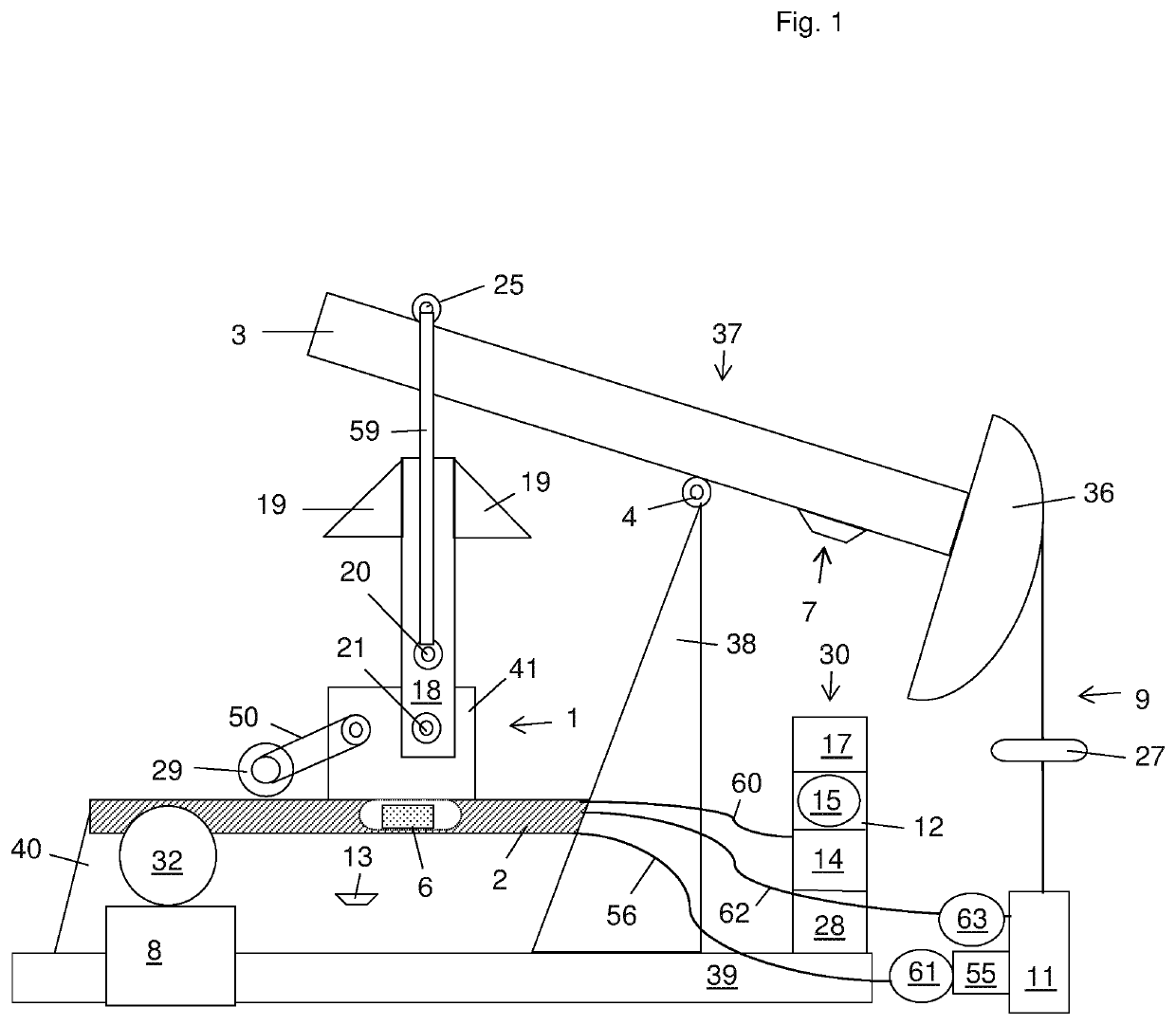
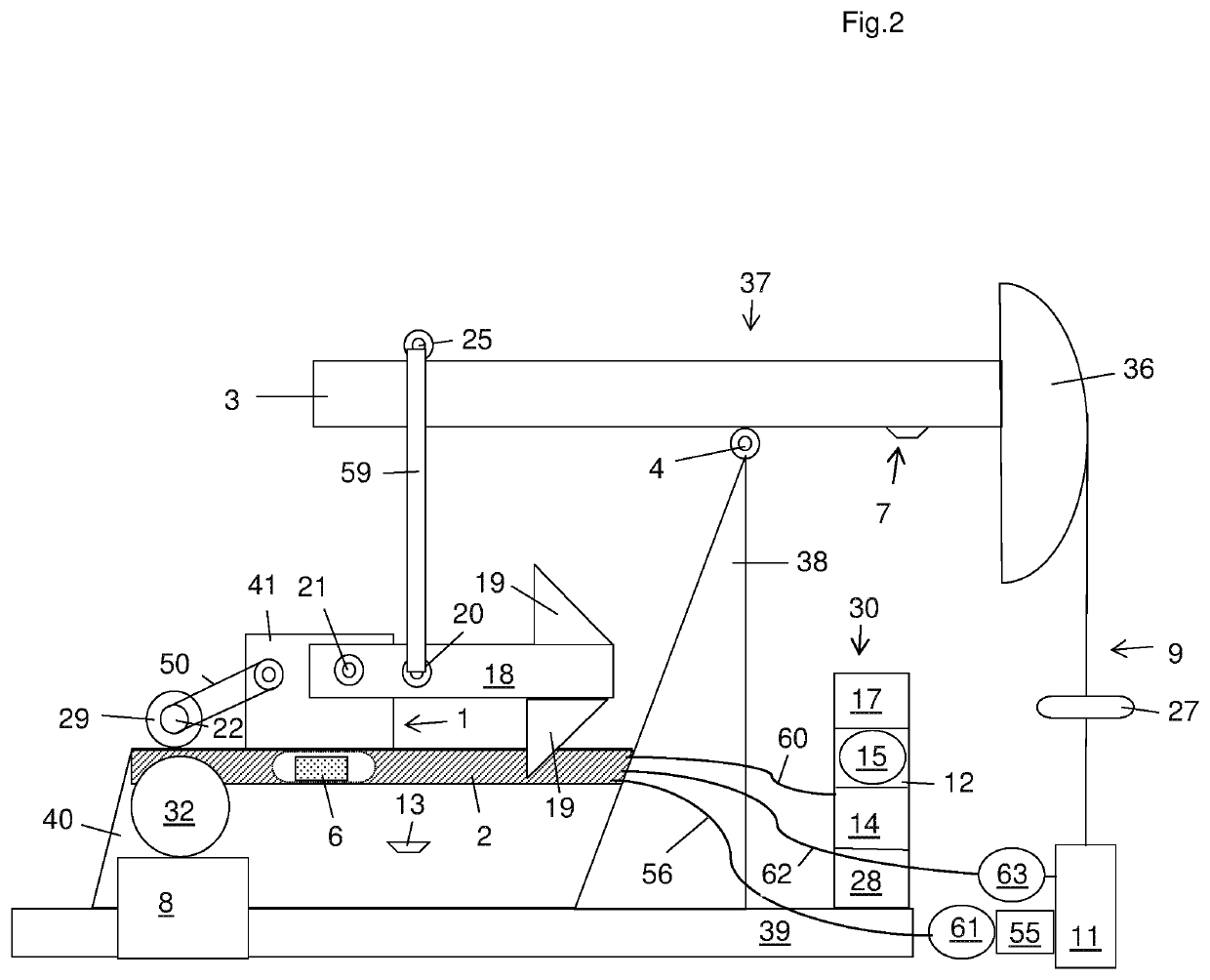
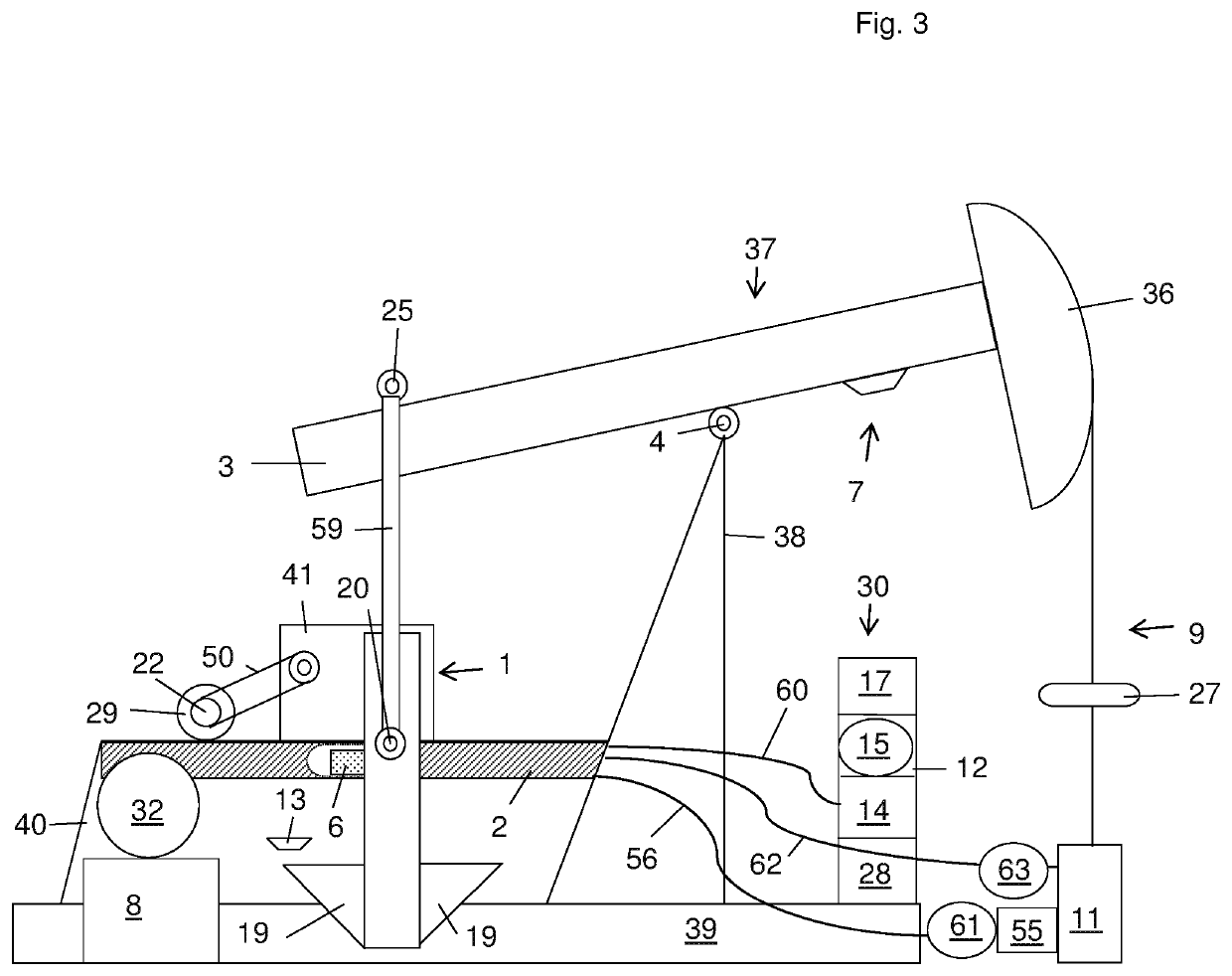
[0017]Embodiments of the present invention relate to lifting and lowering loads more efficiently and also more economically than known systems. This invention is the continuous movement by mechanical means of a moving crank shaft force point to a desired advantageous position at a desired advantageous moment to achieve improved geometry resulting in a desired low torque factor for a reduced net torque when lifting or lowering an unbalanced load with a beam with a fulcrum and connected to a load and an effort.
[0018]In one embodiment, a walking beam well pumping unit, the lifting and lowering of the well load can be caused by the reciprocating motion of a beam tipping on a fulcrum and with an effort force point.
[0019]Potentially reduced net torque might allow longer life speed reducers, smaller speed reducers, and longer reciprocating vertical stroke length and these are both economic and performance benefits.
[0020]Objects, advantages and novel features, and further scope of applicabi...
PUM
 Abstract
Description
Claims
Application Information