
Optimization approach to load balancing and minimization of build time in additive manufacturing

a technology of additive manufacturing and optimizer, applied in the direction of additive manufacturing processes, manufacturing tools, manufacturing data acquisition/processing, etc., can solve the problems of saving labor cost and time spent on manual or simple assignment development, and achieve the effect of reducing the overall completion time, increasing the throughput of the additive machine, and saving labor cost and time spen

Active Publication Date: 2021-07-20
GENERAL ELECTRIC CO
View PDF13 Cites 0 Cited by
  • Summary
  • Abstract
  • Description
  • Claims
  • Application Information

AI Technical Summary

Benefits of technology

This invention is about a new way to make parts using 3D printing. It helps to determine the best way to laser scan the material and assign the lasers to the regions of the part. This makes the process faster and more efficient. It also automates the assignment of lasers to regions, saving time and money. It uses data on the exact layout of the laser scan field and takes into account the impact of smoke on the quality of the part. Overall, this invention makes it possible to make better parts faster and more accurately.

Problems solved by technology

Another technical effect of some embodiments is an automated way of assigning lasers-to-regions, thus saving on labor cost and time spent in developing the assignment manually or simple rule-based approaches.

Method used


Image

  • Optimization approach to load balancing and minimization of build time in additive manufacturing
  • Optimization approach to load balancing and minimization of build time in additive manufacturing
  • Optimization approach to load balancing and minimization of build time in additive manufacturing

Examples


Embodiment Construction

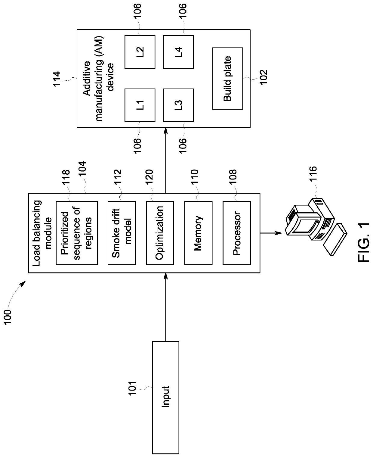
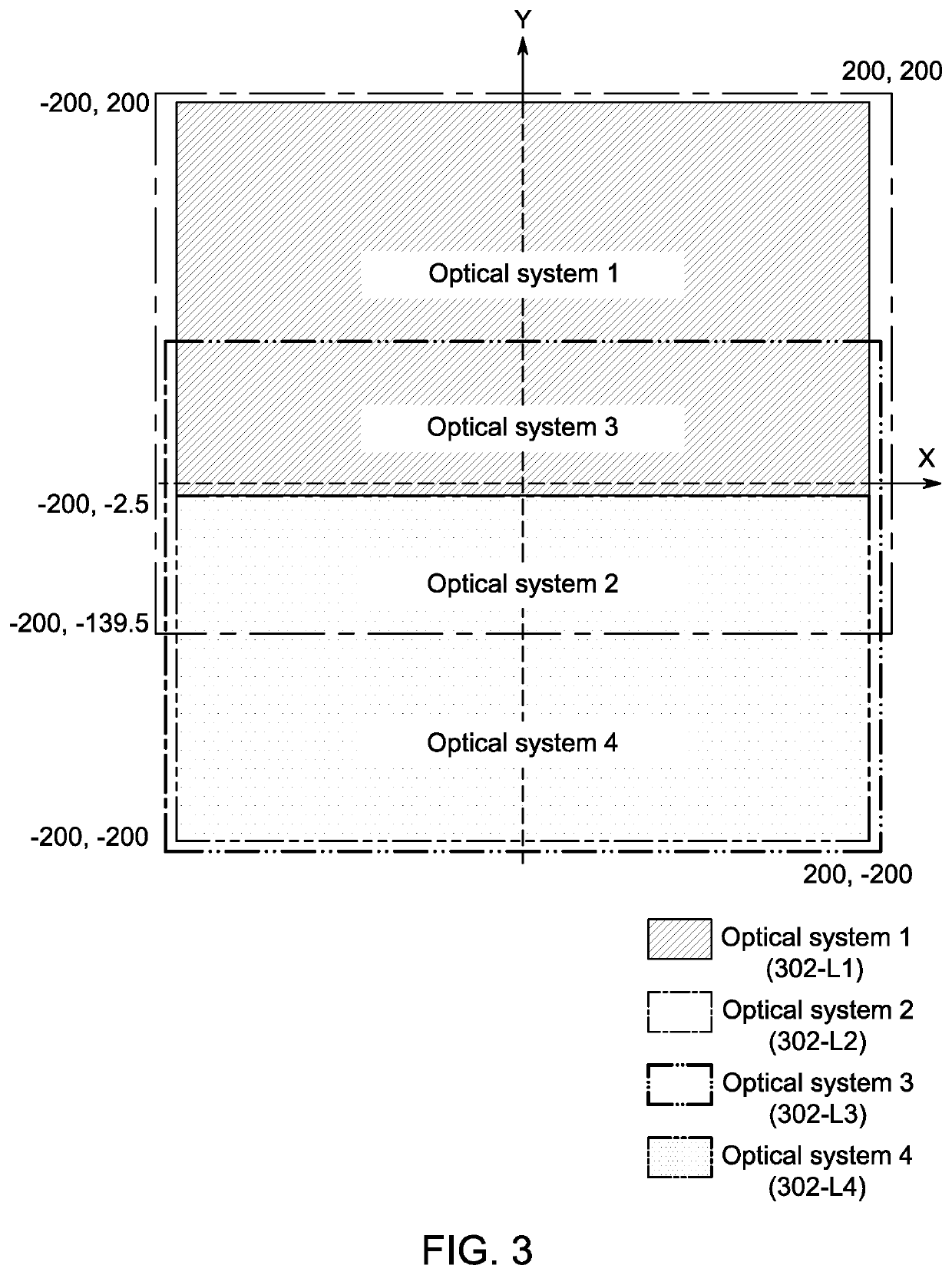
[0018]An example of an AM process is called powder-based melting. In this technology, laser beams are used to melt powdered grains of material on a build plate (“material”) to build one or more parts, layer-by-layer in a controlled three-dimensional space. The material may be, for example, polymers, metals, ceramics, etc. Other suitable materials may be used. To achieve high throughput for a large build area, multiple lasers may work in parallel. Each laser may have a defined scan field boundary (e.g., an area that may be exposed to the laser). There may be overlap in the defined scan field boundaries between two or more lasers. As it is undesirable to have two or more lasers contact the same material on the build plate, when laser scan field boundaries overlap, the lasers may take turns, so that while a first laser is exposing the material to the laser beam, a second laser is idle, for example.

[0019]It is also noted that in some instances a first area of a build plate may have a lo...


PUM

PropertyMeasurementUnit
sizeaaaaaaaaaa
lag timeaaaaaaaaaa
timeaaaaaaaaaa

Abstract

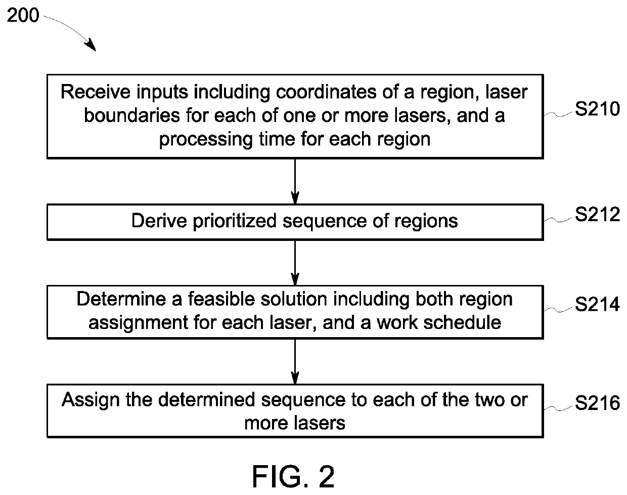
According to some embodiments, system and methods are provided comprising receiving input including: coordinates of one or more regions to be fabricated on a build plate, a laser boundary for each of two or more lasers, wherein the lasers fabricate the one or more regions, and a processing time for each region; deriving a prioritized sequence of the one or more regions to be fabricated; determining, based on the received coordinates and received laser boundary, one or more potential lasers assignments for each region; determining, based on the determined potential laser assignments, the prioritized sequence of the one or more regions, and the processing time for each region, a laser-to-region sequence for the one or more lasers to fabricate the one or more regions; assigning the determined laser-to-region sequence to the one or more lasers for fabrication of the one or more regions. Numerous other aspects are provided.

Description

BACKGROUND[0001]Additive manufacturing (AM) processes are used to fabricate precision three-dimensional components from a digital model. Such components are fabricated using an additive process, where successive layers of material are solidified one on top of the other on a build plate. Some AM systems use a laser (or similar energy source) and a series of lenses and mirrors to direct the laser over a powdered material in a pattern provided by a digital model (powder-bed AM). The laser solidifies the powdered material by sintering or melting the powdered material. To achieve high throughput, multiple lasers may work in parallel, where each laser has a defined area that it may access on the build plate. These defined areas may overlap each other.[0002]A challenge in powder-bed AM is that multiple lasers cannot work on a same area at a same time. To avoid multiple lasers are not working in the same area at the same time, some lasers may be idle while other lasers are working. The buil...

Claims


Application Information

Patent Timeline
Patent Type & Authority Patents(United States)
IPC IPC(8): B29C64/393B29C64/153B29C64/268B22F10/20B33Y10/00B33Y30/00B33Y50/02B22F10/30
CPCB29C64/393B22F10/20B29C64/153B29C64/268B22F10/30B33Y10/00B33Y30/00B33Y50/02B33Y50/00B29C64/171Y02P10/25B22F10/80B22F10/28B22F12/45
Inventor UMANG, NITISHHERTEL, KAIWACKER, CHRISTIANROYCHOWDHURY, SUBHRAJITTOLEDANO, DAVIDBOLLAPRAGADA, SRINIVAS
Owner GENERAL ELECTRIC CO
Learn More