
Magnetic tape having characterized magnetic layer and magnetic recording and reproducing device

a technology of magnetic layer and magnetic recording, which is applied in the field of magnetic recording and reproducing devices, can solve the problems of increasing the distance between the magnetic layer surface and the reproducing element of the head, and generating spacing loss, and achieve the effect of suppressing the decrease of electromagnetic conversion characteristics

Active Publication Date: 2021-07-20
FUJIFILM CORP
View PDF456 Cites 0 Cited by
  • Summary
  • Abstract
  • Description
  • Claims
  • Application Information

AI Technical Summary

Benefits of technology

[0004]One of the performances required for a magnetic tape is that it can exhibit excellent electromagnetic conversion characteristics in a case of reproducing information recorded on the magnetic tape. However, in a case where the surface of the magnetic layer and / or the head is chipped while repeatedly sliding between the magnetic layer surface and the head, a phenomenon (so-called spacing loss) occurs that the distance between the magnetic layer surface and the reproducing element of the head increases. In this regard, as disclosed in JP2005-243162A, for example, inclusion of an abrasive in the magnetic layer can contribute to providing head cleaning properties on the surface of the magnetic layer by the abrasive. By providing head cleaning properties on the surface of the magnetic layer, it is possible to suppress the occurrence of spacing loss due to the foreign matter generated by chipping the surface of the magnetic layer interposed between the surface of the magnetic layer and the head. On the other hand, the higher the head cleaning property of the magnetic layer surface, the easier it is to chip the head due to sliding with the magnetic layer surface, resulting in the generation of spacing loss. Such spacing loss causes a phenomenon in which the electromagnetic conversion characteristics decrease while repeating the reproduction of information recorded on the magnetic tape (hereinafter also referred to as “a decrease in the electromagnetic conversion characteristics in repeated reproduction”).

Problems solved by technology

However, in a case where the surface of the magnetic layer and / or the head is chipped while repeatedly sliding between the magnetic layer surface and the head, a phenomenon (so-called spacing loss) occurs that the distance between the magnetic layer surface and the reproducing element of the head increases.
On the other hand, the higher the head cleaning property of the magnetic layer surface, the easier it is to chip the head due to sliding with the magnetic layer surface, resulting in the generation of spacing loss.

Method used


Image

  • Magnetic tape having characterized magnetic layer and magnetic recording and reproducing device

Examples


example 1

[0138]

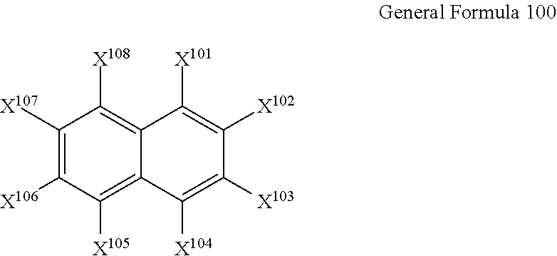
[0139]With respect to 100.0 part of the oxide abrasive (an alumina powder) shown in Table 1, 2,3-dihydroxynaphthalene in the amount shown in Table 1 (manufactured by Tokyo Chemical Industry Co., Ltd.), 31.3 parts of a 32% solution of a polyester polyurethane resin having a SO3Na group as a polar group (UR-4800 manufactured by Toyobo Co., Ltd. (polar group amount: 80 meq / kg)) (solvent is a mixed solvent of methyl ethyl ketone and toluene), and 570.0 parts of a mixed solution of methyl ethyl ketone and cyclohexanone 1:1 (the mass ratio) as a solvent were mixed and dispersed by a paint shaker for the time shown in Table 1 (bead dispersion time) in the presence of zirconia beads (the bead diameter: 0.1 mm). After the dispersion, the centrifugal treatment was performed with respect to the obtained dispersion liquid by separating the dispersion liquid and the beads by the mesh. The centrifugal treatment was performed with CS150GXL manufactured by Hitachi Koki Co., Ltd. (the used rot...

examples 2 , 3 , 5

Examples 2, 3, 5 and Comparative Examples 1 to 8

[0200]A magnetic tape was manufactured in the same manner as in Example 1, except that various conditions shown in Table 1 were changed as shown in Table 1. All of the oxide abrasives listed in Table 1 are alumina powders. In Table 1, in the comparative examples in which “no alignment process” is shown in the column of “formation and alignment of magnetic layer”, the magnetic tape was manufactured without performing the alignment process regarding the coating layer of the magnetic layer forming composition.

example 4

[0201]After forming the non-magnetic layer, the magnetic layer forming composition was applied on the surface of the non-magnetic layer so that the thickness after drying becomes 25 nm to form a first coating layer. The first coating layer was passed through the atmosphere at the atmosphere temperature shown in Table 1 (the drying temperature) without application of a magnetic field to form a first magnetic layer (no alignment process).

[0202]After that, the magnetic layer forming composition was applied on the surface of the first magnetic layer so that the thickness after drying becomes 25 nm to form a second coating layer. The homeotropic alignment process and the drying process were performed by applying a magnetic field having a strength shown in Table 1 in the vertical direction with respect to the surface of the second coating layer using opposing magnet in the atmosphere at the atmosphere temperature shown in Table 1 (the drying temperature) while the second coating layer was...


PUM

PropertyMeasurementUnit
particle diameteraaaaaaaaaa
refractive index Nzaaaaaaaaaa
humidityaaaaaaaaaa

Abstract

Provided are a magnetic tape comprising a magnetic layer containing a ferromagnetic powder and a binding agent on a non-magnetic support, in which the magnetic layer contains an oxide abrasive, an average particle diameter of the oxide abrasive obtained from a secondary ion image acquired by irradiating a surface of the magnetic layer with a focused ion beam is 0.04 μm to 0.08 μm, and an absolute value ΔN of a difference between a refractive index Nxy measured with respect to an in-plane direction of the magnetic layer and a refractive index Nz measured with respect to a thickness direction of the magnetic layer is 0.25 to 0.40, and a magnetic recording and reproducing device including the magnetic tape.

Description

CROSS-REFERENCE TO RELATED APPLICATIONS[0001]This application is a Continuation of PCT International Application No. PCT / JP2018 / 033530 filed on Sep. 11, 2018, which claims priority under 35 U.S.C. § 119(a) to Japanese Patent Application No. 2017-191659 filed on Sep. 29, 2017 and Japanese Patent Application No. 2018-159512 filed on Aug. 28, 2018. Each of the above applications is hereby expressly incorporated by reference, in its entirety, into the present application.BACKGROUND OF THE INVENTION1. Field of the Invention[0002]The present invention relates to a magnetic tape and a magnetic recording and reproducing device.2. Description of the Related Art[0003]Magnetic recording media are divided into tape-shaped magnetic recording media and disk-shaped magnetic recording media, and tape-shaped magnetic recording media, that is, magnetic tapes are mainly used for data storage. The recording of information on a magnetic tape and / or reproducing thereof are normally performed by causing a...

Claims


Application Information

Patent Timeline
Patent Type & Authority Patents(United States)
IPC IPC(8): G11B5/706G11B5/735G11B5/008G11B5/708G11B5/712G11B5/714
CPCG11B5/70678G11B5/00817G11B5/7085G11B5/712G11B5/714G11B5/7358
Inventor IWAMOTO, TAKAHIROHOSODA, HIDEMASAKASADA, NORIHITOKUROKAWA, TAKUTO
Owner FUJIFILM CORP
Learn More