Magnetic recording medium including an amorphous carbon protective film

a technology of amorphous carbon and protective film, which is applied in the field of protective film and a magnetic recording medium, can solve the problems of difficult for conventional technologies to achieve the reduction of the film thickness of the protective film simultaneously, and achieve the improvement of the durability and corrosion resistance of the protective film, the effect of reducing the film thickness of the protective film and improving the bonding strength of the surfa

Active Publication Date: 2015-03-17
FUJI ELECTRIC CO LTD
View PDF15 Cites 0 Cited by
  • Summary
  • Abstract
  • Description
  • Claims
  • Application Information

AI Technical Summary

Benefits of technology

[0015]The present invention can simultaneously accomplish reduction in film thickness of the protective film, improvement of the durability and corrosion resistance of the protective film, and improvement of the bonding strength of the surface of the protective film to the lubricating film. Furthermore, the magnetic recording medium with the protective film can achieve excellent electromagnetic conversion characteristics.
[0016]Better durability and corrosion resistance can be obtained by adding fluorine to a region 0.5 nm deep from the surface of the protective film. When the lubricating film is provided on the surface of the protective film, the lubricating film can be prevented from falling off the surface of the protective film, by adding nitrogen to a region 0.5 nm deep from the surface of the protective film. Setting the film thickness of the protective film at a value equal to or greater than 1.7 nm but equal to or less than 2.3 nm can eliminate the spacing loss with respect to a magnetic head. As a result, excellent electromagnetic conversion characteristics, durability, and corrosion resistance can be realized. Excellent durability and corrosion resistance can be realized by adding the fluorine and nitrogen in an amount of 5 to 20 at. %. Placing the lubricating film on the protective film and setting the film thickness of the lubricating film at a value equal to or greater than 0.6 nm but equal to or less than 1.0 nm can eliminate the spacing loss with respect to the magnetic head and realize excellent electromagnetic conversion characteristics and durability.
[0017]According to the present invention, the fluorine improves the durability and corrosion resistance of the surface of the protective film, and the nitrogen improves the bonding strength of the surface of the protective film to the lubricating film. The inventors of the present invention have discovered that the fluorine for improving the durability and corrosion resistance of the surface of the protective film and the nitrogen for improving the bonding strength of the surface of the protective film can simultaneously exert the beneficial effects thereof by existing in the vicinity of the surface of the protective film. The inventors of the present invention have discovered that the durability and corrosion resistance of the protective film and peel-resistant characteristics of the protective film to the lubricating film can be maintained by using both the fluorine-containing gas and the nitrogen-containing gas when performing gas plasma processing on the protective film. The reason why it has conventionally been difficult to use both fluorine-containing gas and nitrogen-containing gas in a gas plasma process of a protective film is because the use of both fluorine-containing gas and nitrogen-containing gas deteriorates either the beneficial effects exhibited by fluorine or the beneficial effects exhibited by nitrogen. Optimization of conditions for the gas plasma process is taken into special consideration when using both fluorine-containing gas and nitrogen-containing gas in the gas plasma process of the protective film.

Problems solved by technology

Unfortunately, it is difficult for these conventional technologies to simultaneously accomplish reduction in the film thickness of a protective film, improvement of the durability and corrosion resistance of the protective film, and improvement of the bonding strength of the surface of the protective film to a lubricating film.

Method used


Image

  • Magnetic recording medium including an amorphous carbon protective film
  • Magnetic recording medium including an amorphous carbon protective film
  • Magnetic recording medium including an amorphous carbon protective film

Examples


example

Example 1

[0044]First of all, an underlayer, intermediate layer, and magnetic recording layer were sequentially stacked on an aluminum substrate having a diameter of 95 mm and a thickness of 1.75 mm, to form a film formation substrate. The underlayer was made from CoZrNb and had a film thickness of 40 nm. The intermediate layer was made from Ru and had a film thickness of 15 nm. The magnetic recording layer was made from CoCrPt—SiO2 and had a film thickness of 15 nm.

[0045]The obtained film formation substrate was installed in a film forming chamber of the filament type plasma CVD apparatus. Ethylene gas was introduced to the film forming chamber at a flow rate of 40 sccm. DC power of 180 V was applied between the cathode filament and an anode. Thermoelectrons were discharged from the cathode filament, to generate ethylene plasma. The pressure inside the film forming chamber was 0.53 Pa. A bias voltage of −120 V (to the ground) was applied to the film formation substrate, to deposit a...

example 2

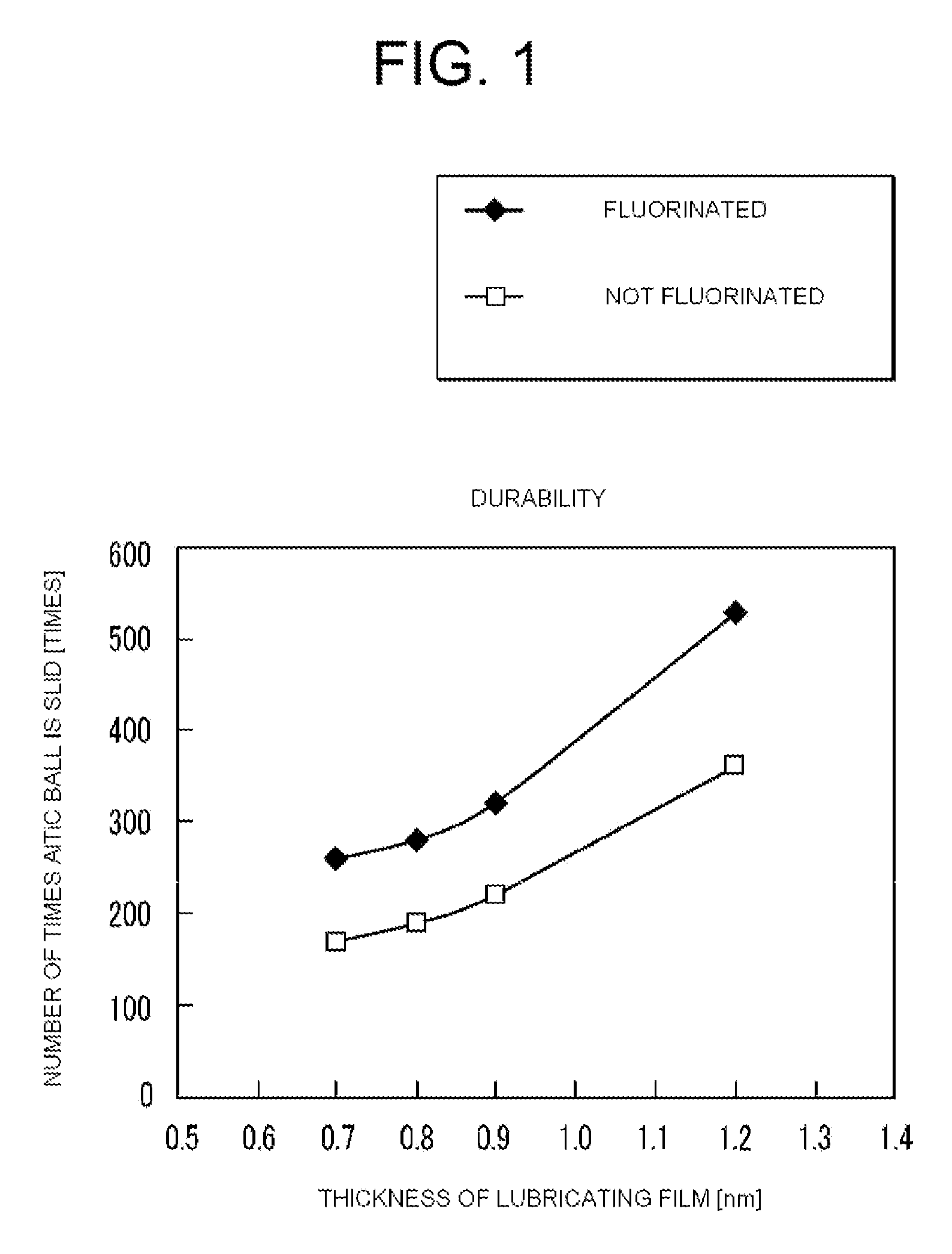
[0051]In the same manner as Example 1, a protective film with a film thickness of 2.2 nm was formed. The surface of the DLC film was nitrided and fluorinated in the same manner as Example 1. The drawing speed of the dip method was adjusted, and a liquid lubricant that mainly contains perfluoropolyether was applied to the protective film to form a lubricating film having a film thickness of 0.8 nm and a lubricating film having a film thickness of 0.7 nm.

[0052]An AITiC ball with a diameter of 2 mm was slid along each of these samples prepared in the manner described above, with a predetermined load and at a predetermined linear velocity, to measure how many times the AITiC ball needed to be slid until the protective film would break. With these samples of the present example, it took a large count of 280 times and 260 times respectively to break the protective film. This result indicates that the samples of the present example have excellent durability.

example 3

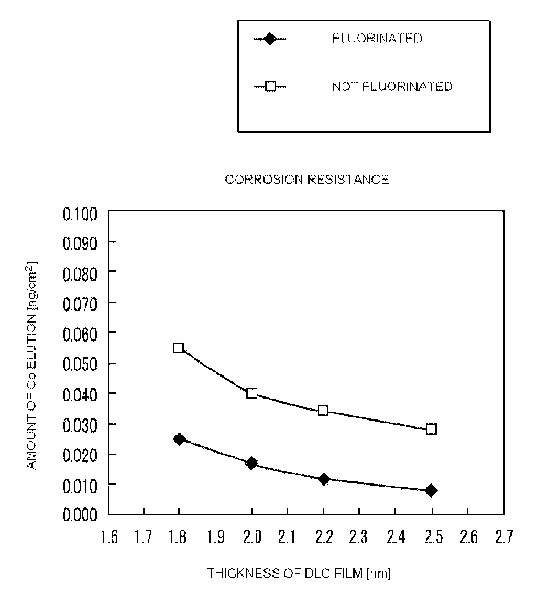
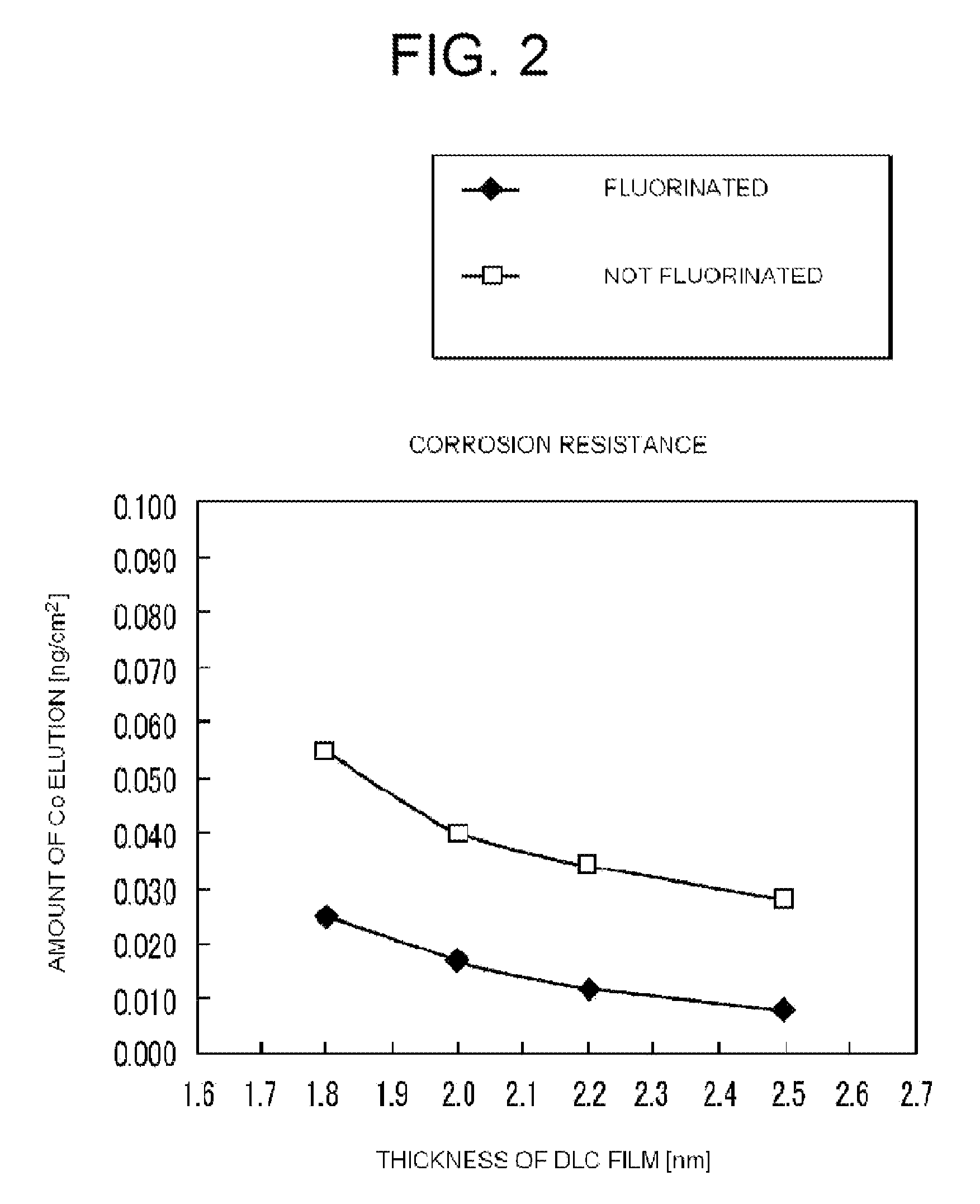
[0053]Using the same method as in Example 1, the film formation time was adjusted, and a DLC film with a film thickness of 2.0 nm and a DLC film with a film thickness of 1.8 nm were formed. The surface of each of these DLC films was nitrided and fluorinated in the same manner as Example 1. The fluorine was added in an amount of 10 at. %. The nitrogen was added in an amount of 10 at. %.

[0054]A liquid lubricant that mainly contains perfluoropolyether was applied to the protective film obtained in the manner described above by using the dip method, to form a lubricating film having a film thickness of 0.9 nm.

[0055]Nitric acid aqueous solution of a predetermined concentration was dropped on the sample that was prepared in the manner described above and then extracted, to measure the amount of Co elution by means of the ICP-MS. The amount of Co elution in the sample of the present example was as low as 0.017 ng / cm2 and 0.025 ng / cm2 respectively. This result indicates that the sample of t...


PUM

PropertyMeasurementUnit
thicknessaaaaaaaaaa
thicknessaaaaaaaaaa
thicknessaaaaaaaaaa

Abstract

A magnetic recording medium includes a substrate; a metal film layer disposed on the substrate; a protective film disposed on the metal film layer; and a lubricant film disposed on a surface of the protective film. The protective film is composed of amorphous carbon containing fluorine and nitrogen in a surface region, and a region deeper than 0.5 nm deep from the surface of the protective film is substantially free from the fluorine and nitrogen. The fluorine and nitrogen may be each added in an amount of 5 to 20 at. %. The present invention simultaneously accomplishes a reduction in film thickness, an improvement in durability and corrosion resistance, and an improvement of the bonding strength of the surface of the protective film to the lubricating film.

Description

BACKGROUND OF THE ART[0001]1. Field of the Invention[0002]The present invention relates to a protective film and a magnetic recording medium having the protective film.[0003]2. Background of the Related Art[0004]A hard coating made of various materials is used as a coating on a sliding resistance member or an antifriction member. A diamond-like carbon (DLC) film made from carbon has been known as such a hard coating. The DLC film is suitable as a surface coating due to its excellent surface smoothness and high hardness. Conventionally, DLC films are formed by a sputtering method, plasma CVD method, and the like.[0005]A magnetic recording medium generally includes a protective film composed of a DLC film on a magnetic recording layer, the DLC film being formed by a plasma CVD method. The protective film is formed for the purpose of protecting the magnetic recording layer from corrosion and being damaged by a magnetic head that comes into contact with or slides on the magnetic recordi...

Claims


Application Information

Patent Timeline
Patent Type & Authority Patents(United States)
IPC IPC(8): G11B5/66C23C16/26G11B5/72G11B5/725
CPCG11B5/72C23C16/26G11B5/725Y10T428/265G11B5/7257G11B5/7268G11B5/7266
Inventor NAGATA, NARUHISAKOBAYASHI, RYOJISUZUKI, YOSHIHISA
Owner FUJI ELECTRIC CO LTD
Why Eureka
Try Eureka