Hinge and method for opening and closing a hinge

a technology of hinges and hinges, applied in the field of hinges, can solve the problems of large installation space in the side parts, and achieve the effect of small installation space and optimized damping behavior

Active Publication Date: 2021-07-27
HETTICH ONI
View PDF27 Cites 1 Cited by
  • Summary
  • Abstract
  • Description
  • Claims
  • Application Information

AI Technical Summary

Benefits of technology

[0004]It is therefore the object of the present invention to provide a h

Problems solved by technology

Such a linear damper is well suitable for damping a closing movement, but the problem results that

Method used


Image

  • Hinge and method for opening and closing a hinge
  • Hinge and method for opening and closing a hinge
  • Hinge and method for opening and closing a hinge

Examples


Embodiment Construction

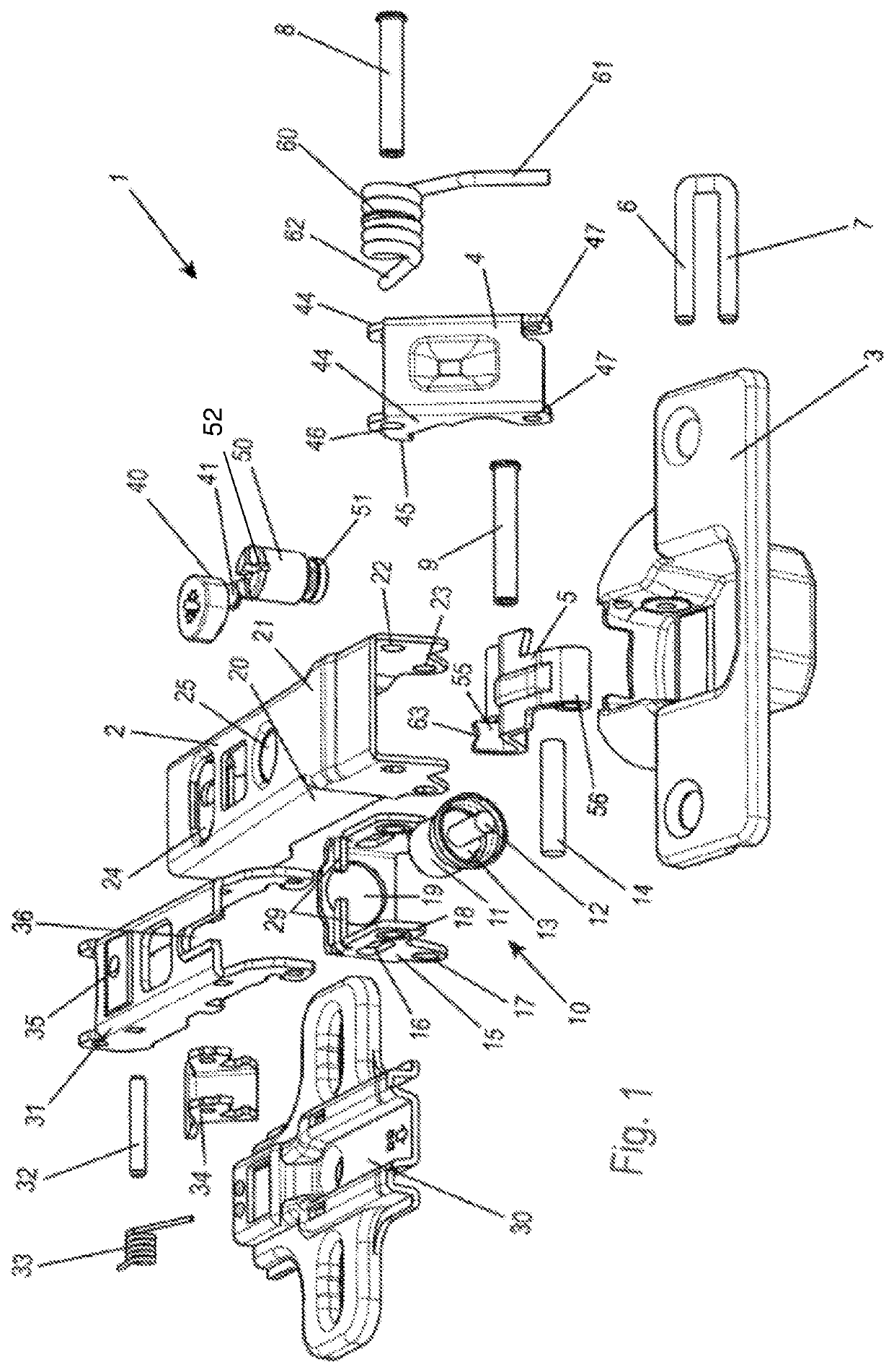
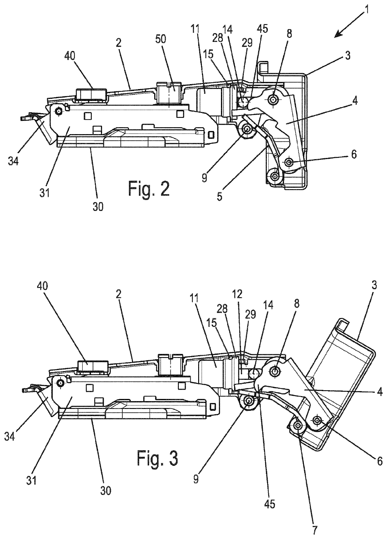
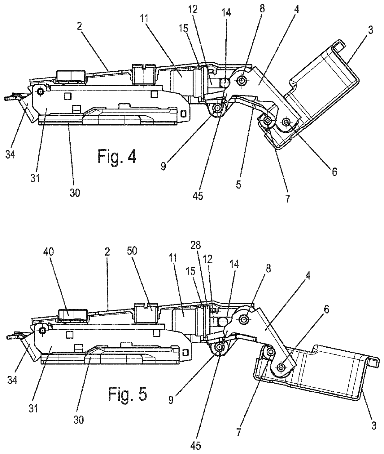
[0024]A hinge 1, in particular for furniture or domestic appliances, comprises a side part 2, which is fixable on a side wall of a furniture body or on another wall. A hinge part 3 is pivotably mounted on the side part 2, on which hinge part a door can be fixed, which is pivotable via the hinge 1 from a closed position into an open position. For this purpose, two levers 4 and 5 are provided between the side part 2 and the hinge part 3. The lever 4 is formed U-shaped, wherein the lever 4 comprises lateral webs 44. The lever 4 comprises openings 47 on the webs 44 in this case, through which an axis 6 is inserted to mount the lever 4 rotatably on the hinge part 3. Furthermore, a spaced-apart axis 7 is also integrally formed with the axis 6, which is inserted through an eye 56 on the lever 5 to mount the lever 5 rotatably on the hinge part 3. The lever 5 can also consist of multiple individual flat parts, which result in a lever 5 having corresponding holes for the axes 7 and 9 when lai...


PUM


Abstract

A hinge has a side part fixable on a wall and a hinge part, which is pivotable in relation to the side part and is fixable on a door. Two levers are provided on the side part and the hinge part, which are each rotatably mounted on the side part and on the hinge part, and a linear damper having a housing and a piston rod is arranged in the side part.

Description

CROSS REFERENCE TO RELATED APPLICATIONS[0001]This application is the National Stage of PCT / EP2018 / 065604 filed on Jun. 13, 2018, which claims priority under 35 U.S.C. § 119 of German Application No. 10 2017 114 473.0 filed on Jun. 29, 2017, the disclosures of which are incorporated by reference. The international application under PCT article 21(2) was not published in English.BACKGROUND OF THE INVENTION[0002]The present invention relates to a hinge having a side part fixable on a wall and a hinge part, which is pivotable in relation to the side part and is fixable on a door, wherein two levers are provided on the side part and the hinge part, which are each rotatably mounted on the side part and on the hinge part, and a linear damper arranged in the side part having a housing and a piston rod. [0003]DE 20 2006 003 196 U discloses a furniture hinge, in which a hinge part is pivotably mounted on a side part via a support lever and a guide lever. A cantilever is formed on the guide le...

Claims


Application Information

Patent Timeline
IPC IPC(8): E05F1/08E05F5/00E05D3/14E05D11/10
CPCE05F5/006E05D3/142E05D11/1021E05Y2201/21E05Y2201/256E05Y2201/264E05Y2900/20E05Y2201/412E05Y2201/424E05Y2201/638
Inventor STUKE, KAI MICHAELSCHNEIDER, MARKPOISCHBEG, JENSFILGES, KARSTENHEINZ, ALEXANDER
Owner HETTICH ONI
Why Eureka
Try Eureka