
Spur cancellation for spur measurement

a spur and spur technology, applied in the field of spur cancellation, can solve the problems of unwanted spurious tones in signals generated by phase-locked loops and other timing circuits

Active Publication Date: 2021-08-17
SKYWORKS SOLUTIONS INC
View PDF69 Cites 3 Cited by
  • Summary
  • Abstract
  • Description
  • Claims
  • Application Information

AI Technical Summary

Problems solved by technology

Signals generated by phase-locked loops and other timing circuits can include undesirable spurious tones.

Method used


Image

  • Spur cancellation for spur measurement
  • Spur cancellation for spur measurement
  • Spur cancellation for spur measurement

Examples


Embodiment Construction

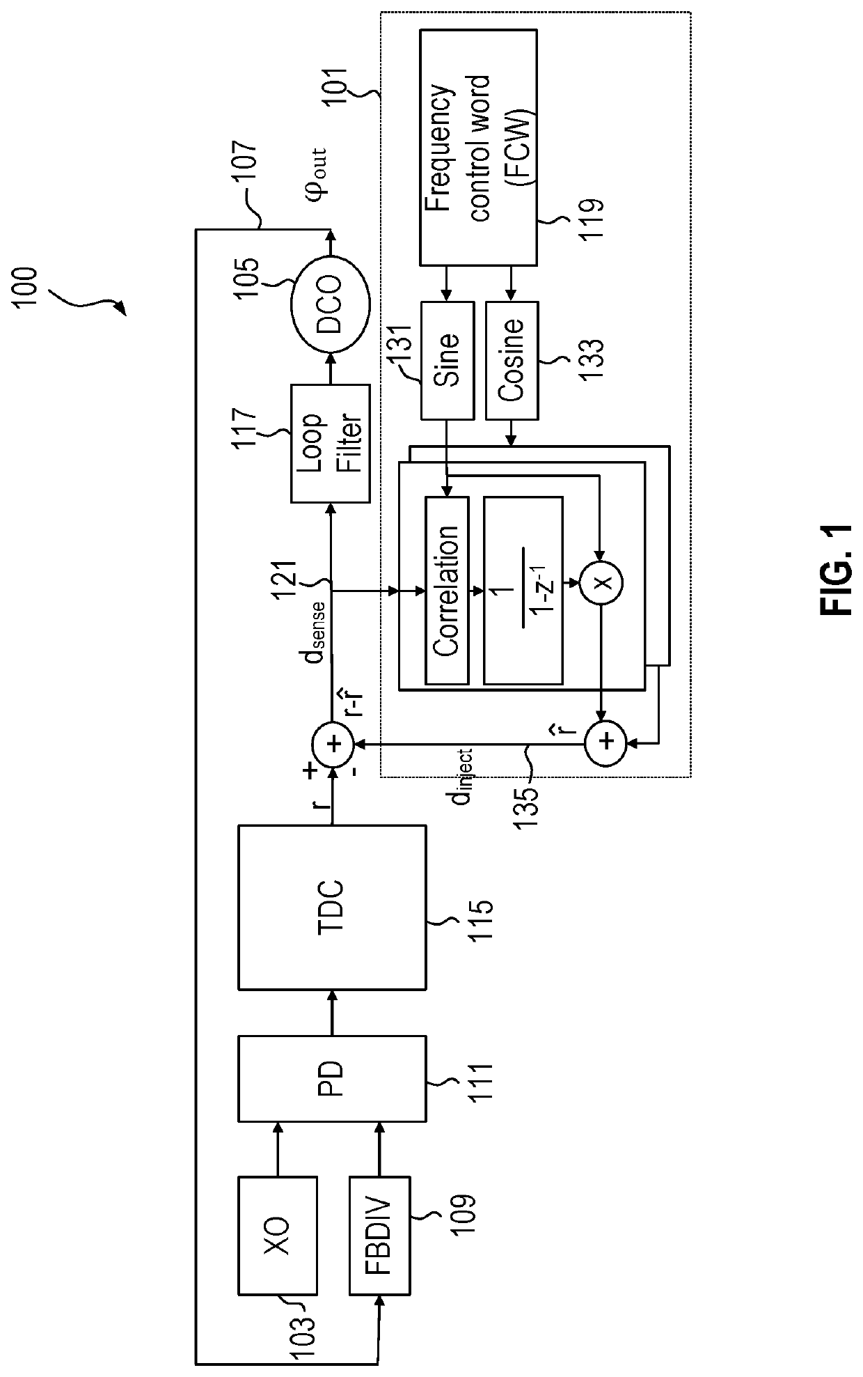
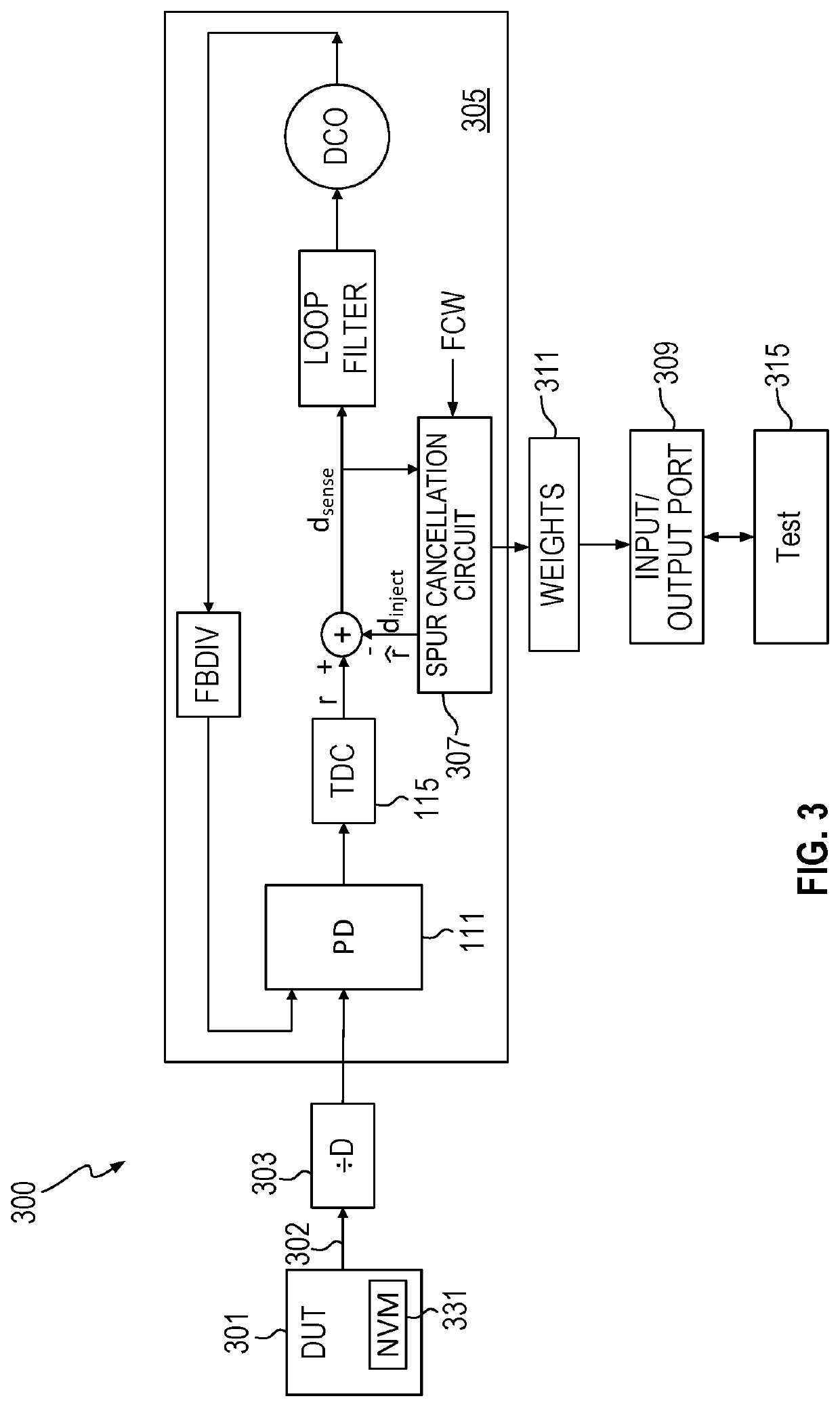
[0003]A first device is supplied with a first frequency control word identifying a first frequency corresponding to a spurious tone of interest to be measured in a first signal generated by a device under test. A phase-locked loop (PLL) of the first device generates a second signal based on the first signal. Presence of the spurious tone in the second signal is determined using a spur cancellation circuit in the first device.

[0004]In another embodiment a spur measurement system includes a first device having a spur cancellation circuit responsive to a frequency control word identifying a spurious tone of interest to be measured in a first signal received by the first device. The spur cancellation circuit is configured to cancel the spurious tone in a second signal in the first device, the second signal based on the first signal. A storage location in the first device stores information generated in the spur cancellation circuit and used to cancel the spurious tone. A first magnitude...


PUM


Abstract

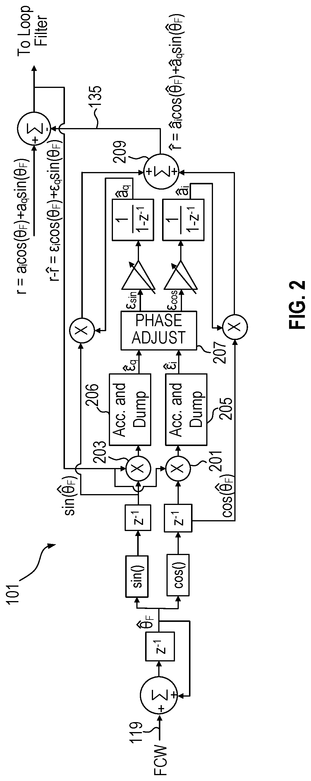
A spur measurement system uses a first device with a spur cancellation circuit that cancel spurs responsive to a frequency control word identifying a spurious tone of interest. A device under test generates a clock signal and supplies the clock signal to the first device through an optional divider. The spur cancellation circuit in the first device generates sine and cosine weights at the spurious tone of interest as part of the spur cancellation process. A first magnitude of the spurious tone in a phase-locked loop in the first device is determined according to the sine and cosine weights and a second magnitude of the spurious tone in the clock signal is determined by the first magnitude divided by gains associated with the first device.

Description

BACKGROUNDField of the Invention[0001]This application relates to measurement of spurious tones.Description of the Related Art[0002]Signals generated by phase-locked loops and other timing circuits can include undesirable spurious tones. Accurately identifying the existence of spurious tones in a testing environment can help ensure that the parts being supplied do not generate significant spurious tones at frequencies of interest. Accordingly, improved measurement techniques for spurious tones are desirable.SUMMARY OF EMBODIMENTS OF THE INVENTION[0003]A first device is supplied with a first frequency control word identifying a first frequency corresponding to a spurious tone of interest to be measured in a first signal generated by a device under test. A phase-locked loop (PLL) of the first device generates a second signal based on the first signal. Presence of the spurious tone in the second signal is determined using a spur cancellation circuit in the first device.[0004]In another...

Claims


Application Information

Patent Timeline
Patent Type & Authority Patents(United States)
IPC IPC(8): H03L7/093G01R29/26G04F10/00G01R31/317
CPCH03L7/093G01R29/26G01R31/31727G04F10/005H03J2200/11H03L7/22H03L7/146
Inventor MONK, TIMOTHY A.THIRUGNANAM, RAJESH
Owner SKYWORKS SOLUTIONS INC
Learn More