Hair cutter blade gap adjustment system

a technology of adjustment system and blade, which is applied in the field of hair cutters, can solve the problems of additional operator difficulty, difficult operation in and of itself, and angulation of one blade relative to the other, and achieve the effect of easy controllable cutting

Active Publication Date: 2021-08-31
CONAIR CORP
View PDF40 Cites 4 Cited by
  • Summary
  • Abstract
  • Description
  • Claims
  • Application Information

AI Technical Summary

Benefits of technology

[0004]Accordingly, the present disclosure is directed to further improvements in hair clippers, shavers, trimmers, etc. For example, illustrative embodiments of the present disclosure permit adjustment of the blade cut while the blades are mounted to the handle. In exemplary embodiments, the present invention further ensures direct relati

Problems solved by technology

Several deficiencies are inherent in conventional clipper designs.
This operation is difficult in and of itself.
Compounding the issue is that the adjustment of the blades often results in

Method used


Image

  • Hair cutter blade gap adjustment system
  • Hair cutter blade gap adjustment system
  • Hair cutter blade gap adjustment system

Examples


Embodiment Construction

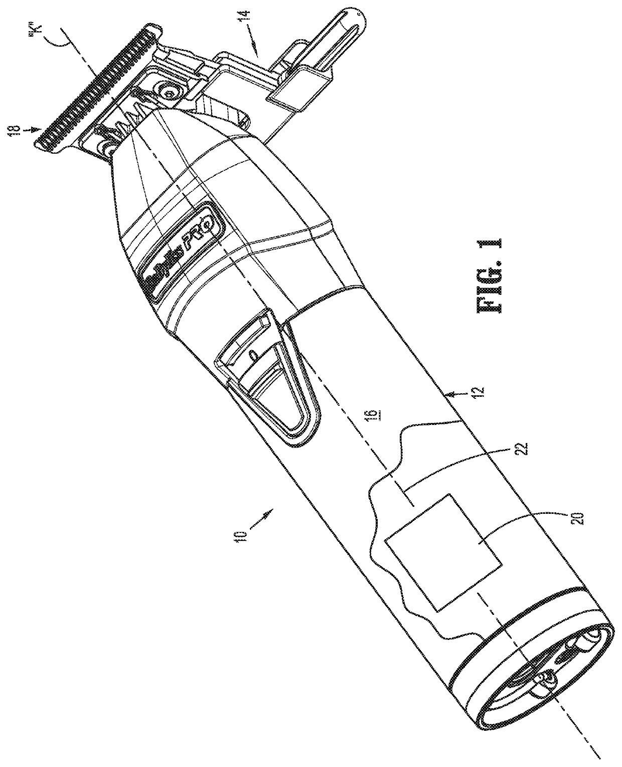
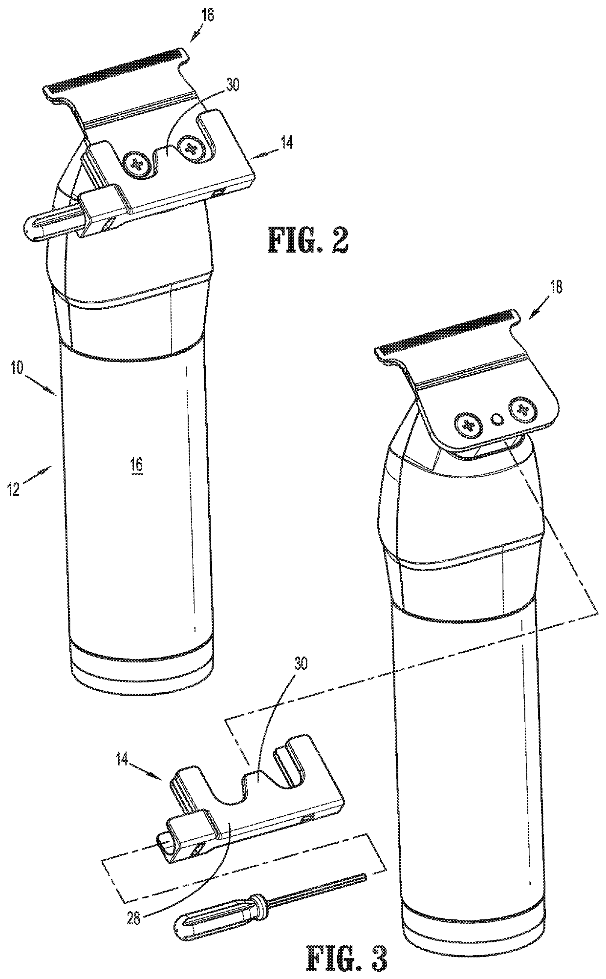
[0027]Referring now to the drawing figures wherein like reference numerals identify similar or like components throughout the several views, FIGS. 1-3 illustrate the hair cutting system in accordance with the principles of the present disclosure. The hair cutting system 10 includes a hair cutter 12 and an adjustment tool 14 which is releasably mountable to the hair cutter 12. The hair cutter 12 may be a hair clipper, a shaver, a hair trimmer or any other personal grooming device capable of cutting, trimming, shaving etc., hair from any part of the human body. For simplicity, the device will be referred to hereinafter as a “hair cutter”. The hair cutter 12 includes a handle 16 defining a longitudinal axis “k” and a cutting blade assembly 18 mounted adjacent the remote end of the handle 16. The handle 16 includes a drive mechanism, schematically illustrated in FIG. 1, as reference numeral 20. The drive mechanism 20 may be powered by an external electrical power source connected by an ...


PUM


Abstract

A hair cutting system includes a handle defining a longitudinal axis, a strut mounted to the handle and a hair cutting blade assembly coupled to the strut. The cutting blade assembly includes a stationary blade defining cutting teeth having blade edges and a movable blade defining cutting teeth having blade edges and capable of reciprocal movement relative to the stationary blade in a horizontal direction. The movable blade and the stationary blade are movable relative to each other in a longitudinal direction to adjust a longitudinal position of the movable blade relative to the stationary blade to selectively vary a distance between the blade edges of the stationary blade and the blade edges of the movable blade. A releasable lock is configured to selectively lock and release the stationary blade and the movable blade with respect to each other in the longitudinal direction.

Description

BACKGROUND1. Technical Field[0001]The present disclosure relates to hair cutters, and, in particular, relates to a hair cutting system with an integral blade adjustment mechanism for adjusting the relative gap between blades to thereby vary the cutting length of hair.2. Discussion of Related Art[0002]Electric hair shavers, clippers or trimmers may incorporate a clipper blade assembly having a stationary blade and a reciprocating blade. The stationary blade and the reciprocating blade each have a plurality of teeth along leading edges of the blades. The reciprocating blade oscillates with respect to the stationary blade to trim hair disposed between the teeth. Examples of hair clippers are disclosed in commonly assigned U.S. Pat. No. 6,536,116 to Fung, U.S. Pat. No. 6,742,262 to Rizzuto et al., and U.S. Patent Publication No. 2014 / 0115901A1 to Liao, the entire contents of each disclosure being hereby incorporated by reference herein.[0003]Several deficiencies are inherent in conventi...

Claims


Application Information

Patent Timeline
IPC IPC(8): B26B19/06B26B19/20B26B19/38
CPCB26B19/063B26B19/205B26B19/3846B26B19/06
Inventor CARLUCCI, VITOCOLPITTS, DENNIS J.
Owner CONAIR CORP
Why Eureka
Try Eureka