Seat track mechanism for vehicle

a seat track and vehicle technology, applied in the direction of vehicle components, vehicle arrangements, bus seats, etc., can solve the problems of increasing the actuating force for seat sliding, reducing the lateral clearance, etc., to reduce the actuating force required for movement, reduce the gap between the rails, and prevent the effect of excessive clearan

Active Publication Date: 2021-09-07
HYUNDAI TRANSYS INC
View PDF13 Cites 2 Cited by
  • Summary
  • Abstract
  • Description
  • Claims
  • Application Information

AI Technical Summary

Benefits of technology

[0007]Aspects of present disclosure relate to a seat track mechanism for a vehicle in which the track structure thereof mounted to the bottom of a seat employs a single rail structure, rather than a double rail structure, thereby not only achieving slimness and autonomy associated with design of the seat bottom, but also simplifying the overall structure through a reduction in the number of constituent elements.
[0009]Therefore, the present disclosure also relates to a single rail structure applied to a seat track mechanism for a vehicle that solves the above-described problems while being capable of not only reducing actuating force required for movement of a seat, but also preventing creation of excessive clearance in a stopped state of the seat.
[0010]According to an aspect of the present disclosure, a seat track mechanism for a vehicle includes a lower rail fixed to a body of the vehicle, an upper rail that is mounted to a seat of the vehicle and is movable forward and rearward along the lower rail, a driver for providing an actuating force to move the upper rail forward and rearward along the lower rail, and a locking mechanism mounted to the upper rail and adapted to control a rail gap between the locking mechanism and the lower rail, thereby restraining movement of the upper rail. The locking mechanism may reduce the rail gap when the vehicle seat is in a stopped state to restrain the movement of the upper rail, and increase the rail gap when the vehicle seat is moved by the driver, to release movement restraint of the upper rail.

Problems solved by technology

The single rail structure includes a single center rail and, as such, is disadvantageous in terms of lateral clearance, as compared to the double rail structure including rails installed at opposite lateral ends of the seat bottom.
However, when such a clearance eliminating structure is applied, there may be a problem in that the actuating force for seat sliding should increase.

Method used


Image

  • Seat track mechanism for vehicle
  • Seat track mechanism for vehicle
  • Seat track mechanism for vehicle

Examples


Embodiment Construction

[0043]Hereinafter reference will be made in detail to various embodiments of the present disclosure, examples of which are illustrated in the accompanying drawings and described below. While the present disclosure will be described in conjunction with exemplary embodiments, it will be understood that the present description is not intended to limit the scope of the disclosure to the exemplary embodiments. On the contrary, the present disclosure is intended to cover not only the exemplary embodiments, but also various alternatives, modifications, equivalents, and other embodiments, which may be within the spirit and scope of the present disclosure as defined by the appended claims.

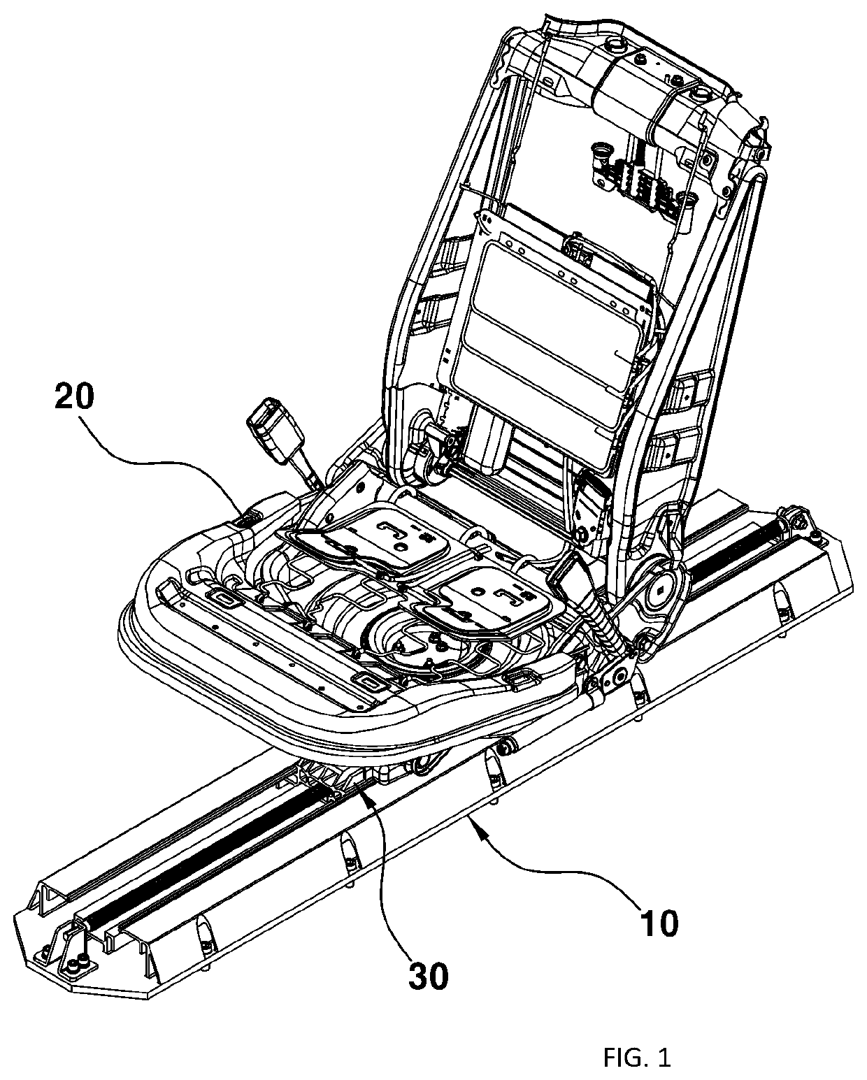
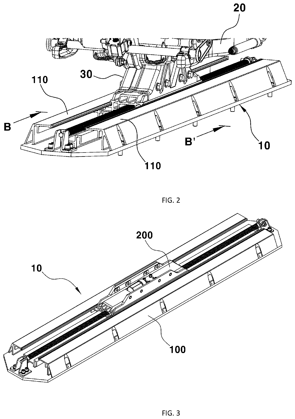
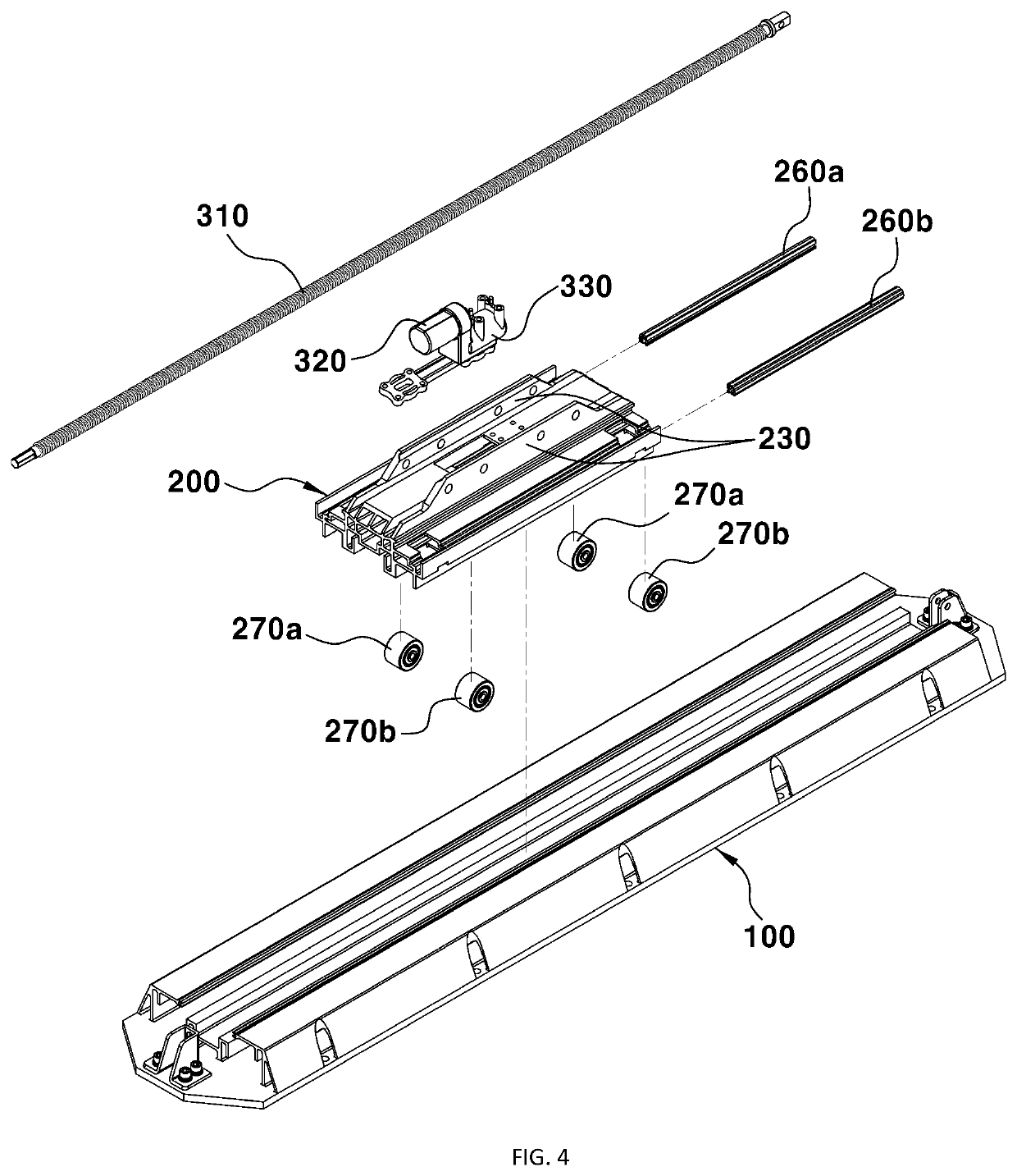
[0044]The present disclosure relates to a seat track mechanism for a vehicle, and more particularly to a seat track mechanism for a vehicle in which a monopost and a monotrack are applied to the bottom of a seat in order to achieve slimness in design of the seat bottom and to secure freedom of movement of t...


PUM


Abstract

A seat track mechanism for installing beneath a vehicle seat in order to move the vehicle seat in the forward and backward directions includes a monotrack mechanism, to which a monopost structure and a single rail structure are applied. The seat track mechanism includes a structure for hook-engaging lower and upper rails constituting the mono track mechanism by hook guides. The single rail structure applied to the seat track mechanism is capable of not only reducing actuating force required for operation, but also preventing creation of excessive clearance upon stopping.

Description

CROSS-REFERENCE TO RELATED APPLICATION[0001]This application claims the benefit of priority under 35 U.S.C. § 119(a) to Korean Patent Application No. 10-2018-0165838 filed on Dec. 20, 2018, the entire contents of which are incorporated herein by reference.BACKGROUND(a) Technical Field[0002]The present disclosure relates generally to a seat track mechanism for a vehicle, and more particularly to a seat track mechanism installed beneath a vehicle seat in order to facilitate movement of the vehicle seat in the forward and backward directions.(b) Background[0003]Various components are provided as part of seat of a vehicle in order to provide enhanced ride comfort and convenience to a driver or passenger. One such component is a seat track mechanism configured to facilitate movement of a seat forward and rearward on the basis of the body form of a driver or passenger sitting thereon. Such a seat track mechanism includes a pair of rails installed beneath a seat at opposite sides of the se...

Claims


Application Information

Patent Timeline
Patent Type & Authority Patents(United States)
IPC IPC(8): B60N2/08B60N2/06B60N2/07B60N2/24
CPCB60N2/08B60N2/067B60N2/0725B60N2/242B60N2/07B60N2/0722B60N2/072B60N2205/20B60N2/0732B60N2/0825B60N2/0862B60N2/0228B60N2/0702B60N2/02253B60N2/02246
Inventor LEE, JAE SUNGMUN, HWA YOUNGLIM, JAE SANG
Owner HYUNDAI TRANSYS INC
Why Eureka
Try Eureka