Display panel having thin film layers with recesses and protrusions

a technology of thin film layers and display panels, applied in the field of display panels, can solve problems such as reducing the service life of display panels, and achieve the effects of increasing the bonding force between thin film layers of display panels, and reducing the service life of display panels

Active Publication Date: 2021-09-07
BAZHOU YUNGU ELECTRONICS TECH CO LTD
View PDF29 Cites 4 Cited by
  • Summary
  • Abstract
  • Description
  • Claims
  • Application Information

AI Technical Summary

Benefits of technology

[0005]The technical problem mainly solved by this disclosure is to provide a display panel, which could enhance the bonding force between thin film layers of the display panel, thereby improving the dynamic bending resistance capability of the display panel, and better preventing the thin film layers from peeling.
[0021]The advantages of the present disclosure are: in the display panel of the present disclosure, the display panel includes a plurality of thin film layers. The plurality of thin film layers may include a first layer and a second layer adjacent to the first layer. The first layer may define a recess at a face toward the second layer. The second layer may comprise a protrusion at a face toward the first layer. The protrusion may be engaged in the recess. A diameter of a tip of the protrusion may be larger than a diameter of a root of the protrusion. A shape of a space in the recess may match with a contour of the protrusion. Therefore, the bonding force between thin film layers of the display panel could be increased, thus the thin film layers could be harder to be peeled when the display panel is bent, and the service life of the display panel could be increased.

Problems solved by technology

When the flexible display panel is bent multiple times, thin film layers in the flexible display panel could easily be peeled, thereby reducing the service life of the display panel.

Method used


Image

  • Display panel having thin film layers with recesses and protrusions
  • Display panel having thin film layers with recesses and protrusions
  • Display panel having thin film layers with recesses and protrusions

Examples


first embodiment

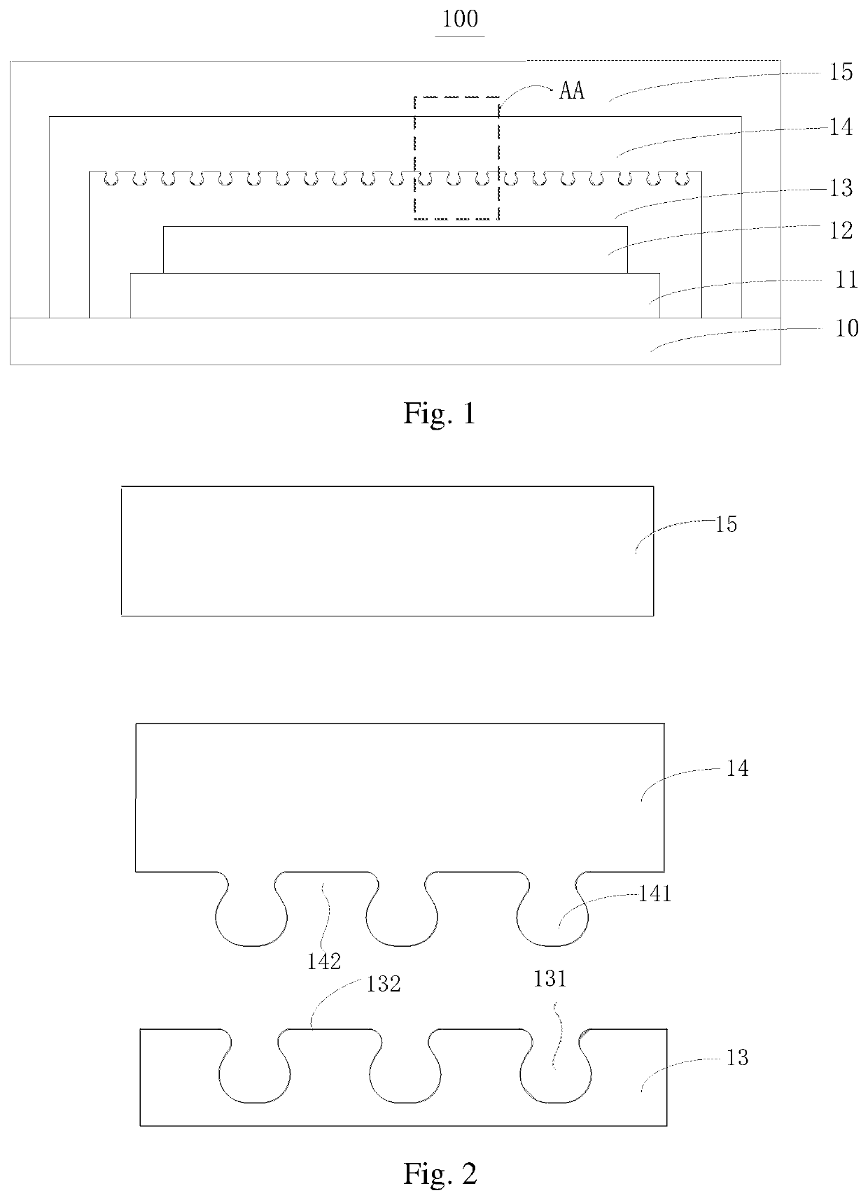
[0035]FIG. 1 is a schematic structural diagram of a display panel according to the present disclosure. As shown in FIG. 1, the display panel 100 may include a substrate 10, a drive layer 11, an organic light emitting layer 12, a first inorganic layer 13, an organic layer 14, and a second inorganic layer 15.

[0036]In this embodiment, the first inorganic layer 13, the organic layer 14, and the second inorganic layer 15 may constitute the encapsulation layer. That is, the encapsulation layer may include multiple layers, i.e., three thin film layers, which are the first inorganic layer 13, the organic layer 14, and the second inorganic layer 15 respectively.

[0037]The drive layer 11 may be disposed on the substrate 10. The organic light emitting layer 12 may be disposed on the drive layer 11. The first inorganic layer 13 may be in contact with the organic light emitting layer 12 and cover the organic light emitting layer 12. The organic layer 14 may cover the first inorganic layer 13. The...

second embodiment

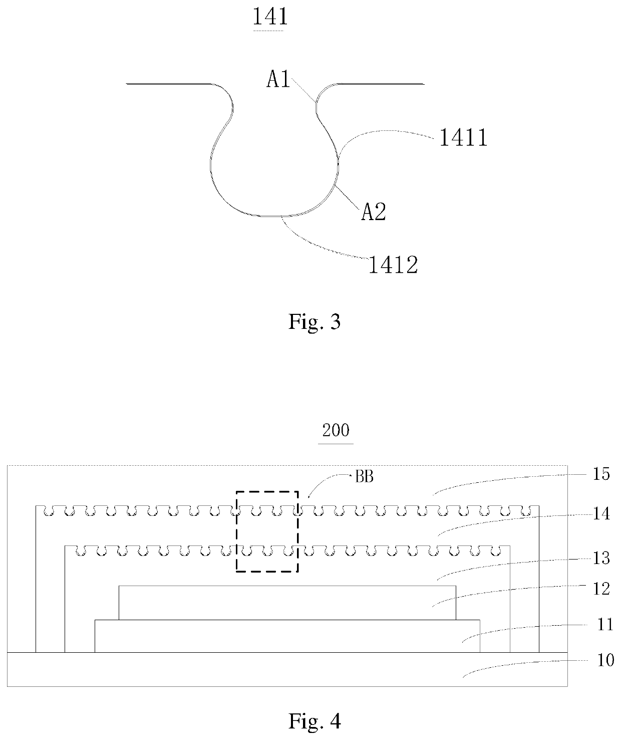
[0047]FIG. 4 is a schematic structural diagram of a display panel 200 according to the present disclosure. FIG. 5 is an explosive schematic structural diagram at BB in the display panel 200 shown in FIG. 4. As shown in FIG. 4 and FIG. 5, the difference between the display panel 200 and the display panel 100 is that: multiple second recesses 143 may be defined at a side face of the organic layer 14 away from the organic light emitting layer 12, multiple second protrusions 151 may be provided on a side face of the second inorganic layer 15 close to the organic light emitting layer 12.

[0048]The second protrusions 151 of the second inorganic layer 15 could be engaged in the second recesses 143 of the organic layer 14, which could enhance the bonding force between the organic layer 14 and the second inorganic layer 15, improve the dynamic bending resistance capability of the display panel 200, and better prevent the encapsulation thin film from peeling.

[0049]The second protrusions 151 ma...

third embodiment

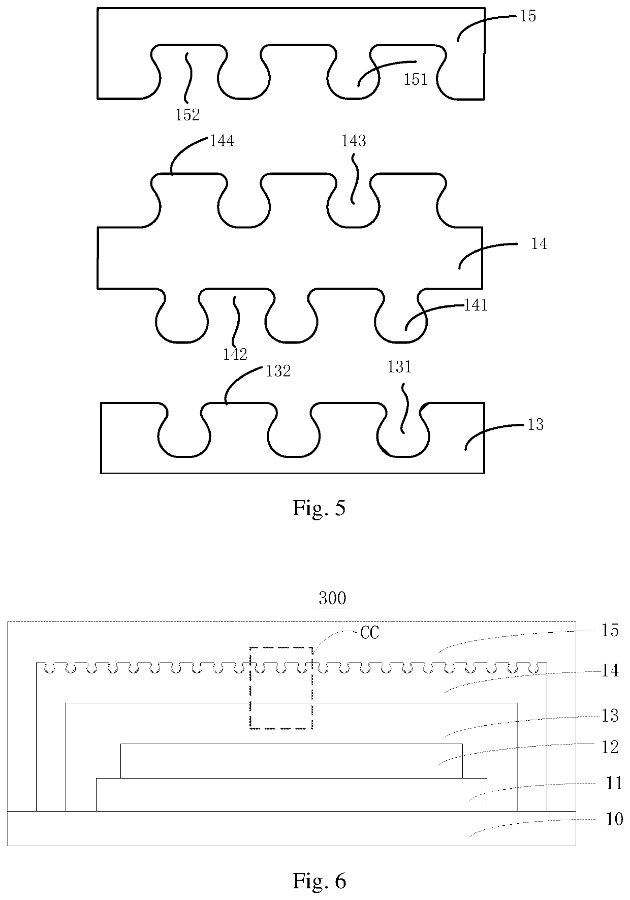
[0059]FIG. 6 is a schematic structural diagram of a display panel 300 according to the present disclosure. FIG. 7 is an explosive schematic structural diagram at CC in the display panel 300 shown in FIG. 6. As shown in FIG. 6 and FIG. 7, the difference between the display panel 300 and the display panel 200 may be that: the first inorganic layer 13 of the display panel 300 does not define the first recesses 131, the organic layer 14 does not include the first protrusions 141. That is, in the display panel 300, the concave-convex engagement may only exist between the second recesses 143 of the organic layer 14 and the second protrusions 151 of the second inorganic layer 15.

[0060]The display panels 300 shown in FIG. 1, FIG. 4 and FIG. 6 is illustrated by an example of an encapsulating layer including three thin film layers, that is an encapsulating layer including a first inorganic layer, an organic layer and a second inorganic layer stacked successively. But this is only schematic. I...


PUM

PropertyMeasurementUnit
diameteraaaaaaaaaa
organicaaaaaaaaaa
depthaaaaaaaaaa

Abstract

The present disclosure discloses a display panel. The display panel may include multiple thin film layers. The multiple thin film layers may include a first layer and a second layer adjacent to the first layer. The first layer may define a recess at a face toward the second layer. The second layer may include a protrusion at a face toward the first layer. The protrusion may be engaged in the recess. A diameter of a tip of the protrusion may be larger than a diameter of a root of the protrusion. A shape of a space in the recess may match with a contour of the protrusion.

Description

CROSS REFERENCE TO RELATED APPLICATION[0001]The present application is a continuation-application of International (PCT) Patent Application No. PCT / CN2019 / 075759 filed on Feb. 21, 2019, which claims foreign priorities of Chinese Patent Application No. 201811162876.0, filed on Sep. 30, 2018 in the National Intellectual Property Administration of China, the entire contents of which are hereby incorporated by reference in their entireties.TECHNICAL FIELD[0002]The present disclosure relates to the field of display technology, and in particular relates to a display panel.BACKGROUND[0003]With the rapid growth of demand for portable mobile devices and wearable display products and the like, the flexible display technology has made great progress in recent years. Among display technologies that could perform flexible display, Organic Light-Emitting Diode (OLED) has excellent performances such as fast response speed, wide view angle, light weight, low power consumption, high brightness, etc....

Claims


Application Information

Patent Timeline
Patent Type & Authority Patents(United States)
IPC IPC(8): H01L51/52H01L51/00H01L27/32H01L33/54H01L33/24
CPCH01L51/5253H01L27/3244H01L51/0097H01L33/24H01L33/54H01L2251/301H01L2251/50H01L2251/5338G09F9/301H10K59/00H10K50/84H10K50/8445Y02E10/549H10K50/844H10K59/12H10K77/111H10K2102/00H10K2102/301H10K2102/311
Inventor XU, YIYINGZHAO, ENTINGSUN, YUANSHENGZHANG, XIANGWEI
Owner BAZHOU YUNGU ELECTRONICS TECH CO LTD
Why Eureka
Try Eureka