
Analysis of wind turbine noise

a technology of wind turbines and noise, applied in the field of wind turbine noise analysis, can solve the problems of wind turbine noise, noise complaints likely to be made, and noise from wind turbines is a well-known problem, and has been the subject of extensive work

Active Publication Date: 2021-09-21
VESTAS WIND SYST AS
View PDF10 Cites 3 Cited by
  • Summary
  • Abstract
  • Description
  • Claims
  • Application Information

AI Technical Summary

Benefits of technology

The patent is about using existing vibration sensors to monitor the condition of a turbine. This reduces the need for new sensors and makes it easier to implement the invention.

Problems solved by technology

Noise emission from wind turbines is a well-known problem and has been the subject of extensive work.
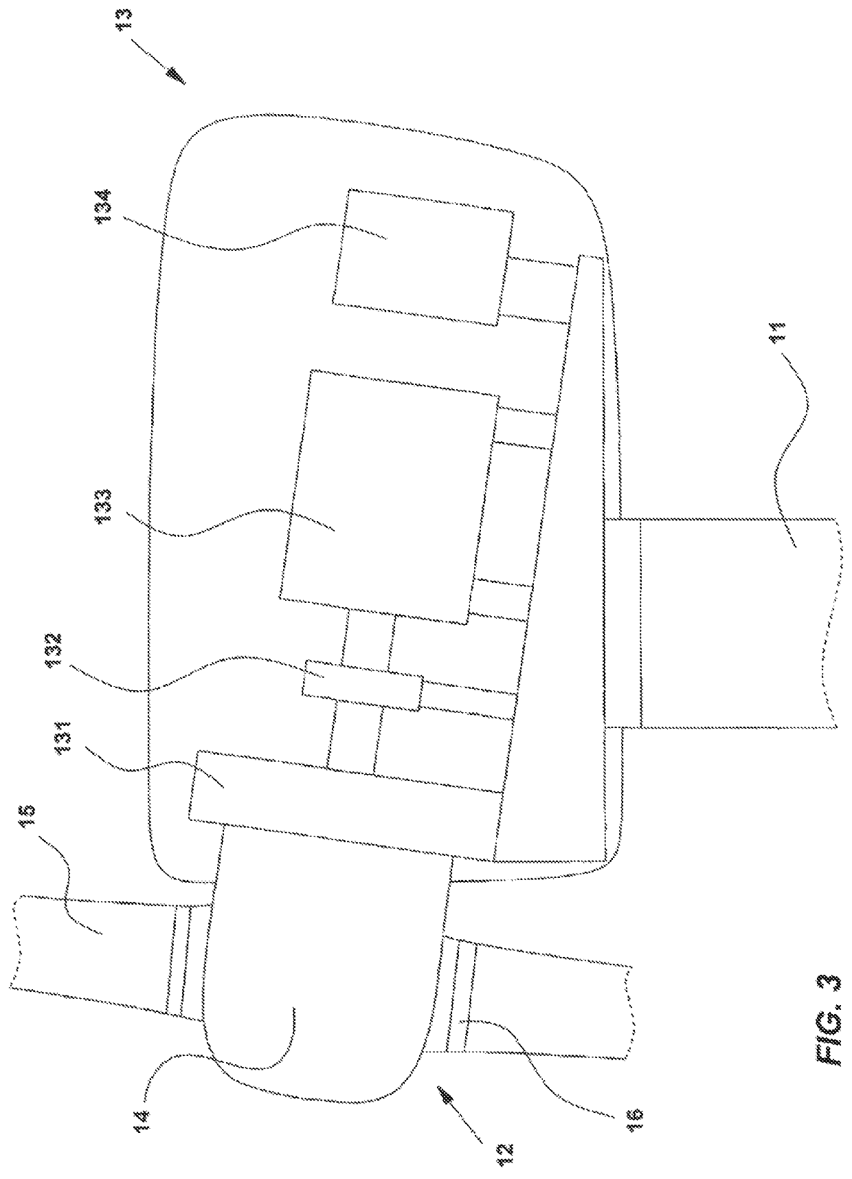
Mechanical noise includes noise produced by components within the nacelle, such as the wind turbine gearbox.
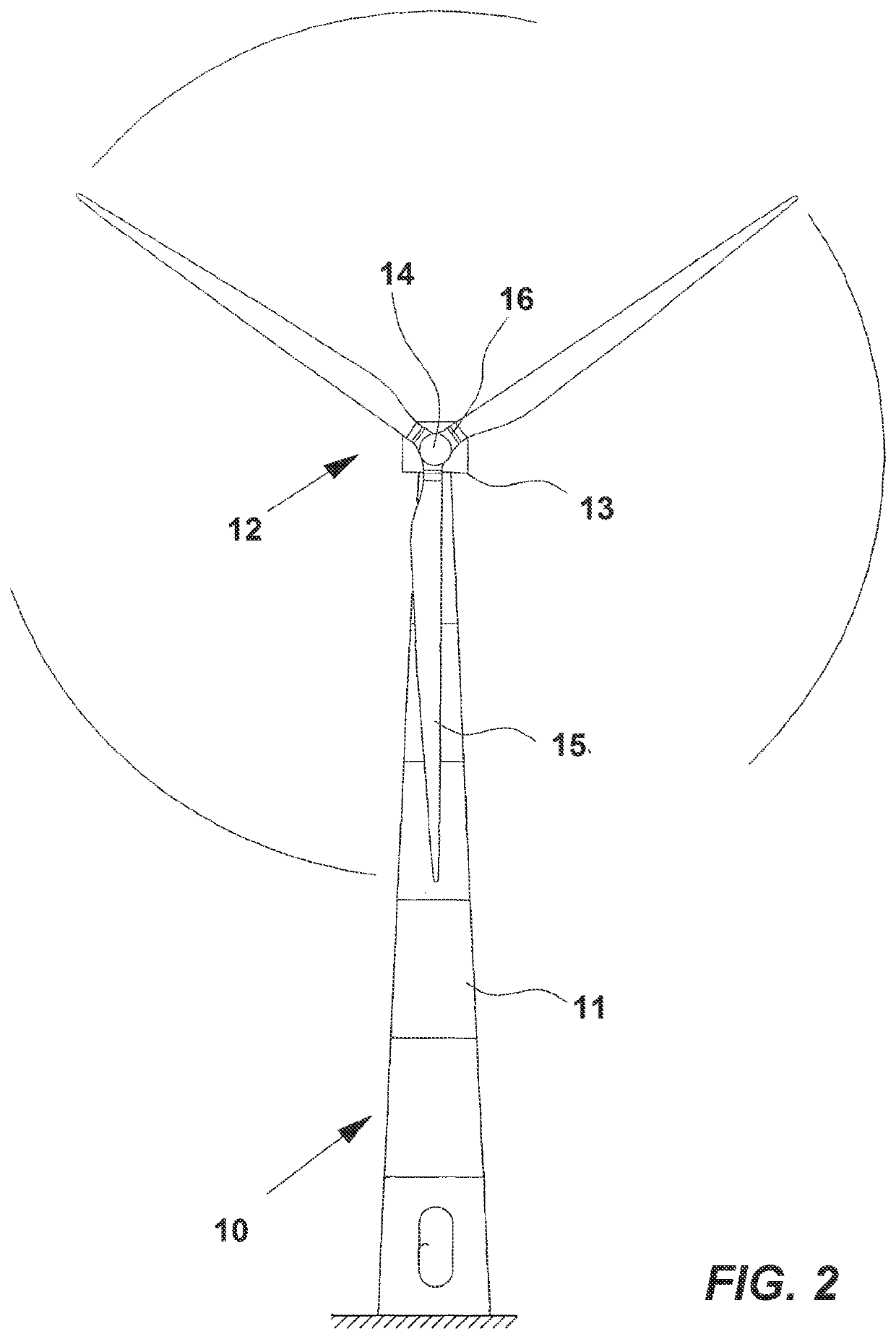
Aerodynamic noise comes from the wind turbine blades and includes, for example, noise due to vortex-shedding.
Noise at distinct frequencies, known as tonal noise, is often perceived as more annoying to wind turbine neighbours and is more likely to be the subject of noise complaints.
Unfortunately, it is difficult to predict when a wind turbine will produce tonal noise and when tonal noise will be audible to wind turbine neighbours as this can depend on a wide variety of factors.
This in turn makes it difficult to evaluate and act on noise complaints made by neighbours, and to adjust the operation of wind turbines to avoid or reduce the production of tonal noise.
As explained above, tonal noise is difficult to predict.
Noise emission models such as those described in EP 2337952 are less effective for predicting tonal noise and identifying tonal noise events.

Method used


Image

  • Analysis of wind turbine noise
  • Analysis of wind turbine noise
  • Analysis of wind turbine noise

Examples


Embodiment Construction

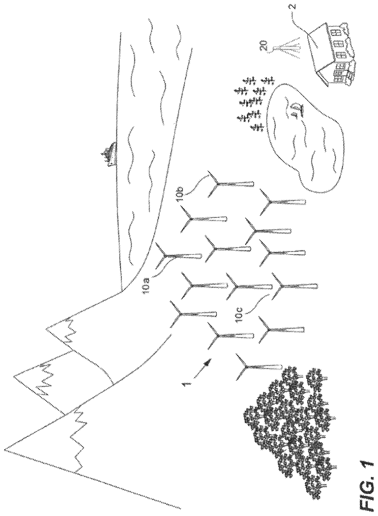
[0039]FIG. 1 illustrates a wind power plant (1) including a number of wind turbines (10a, 10b, 10c) and a neighbouring area (2) in which wind turbine noise is audible. For the purposes of implementing the present invention, the wind power plant (1) can have any number of wind turbines greater than or equal to one, and the wind turbines can be wind turbine models known in the art.

[0040]In the vicinity of the neighbouring area (2), or on or nearby a respective wind turbine, there is a microphone (20) configured to capture noise data, including data representative of the noise produced by one or more of the wind turbines (10a, 10b, 10c) of the wind power plant. The microphone captures noise data over a broad frequency spectrum and an extended time period with a suitable sampling rate, for example in accordance with the procedure described in the third edition of IEC 61400-11.

[0041]The noise data captured by the microphone (20) is communicated from the microphone for analysis. For examp...


PUM


Abstract

A method of analyzing wind turbine noise is provided. The method comprises acquiring noise data representing noise produced by a wind turbine and acquiring data from a plurality of vibration sensors positioned at different locations about the wind turbine. The method further comprises identifying a region of interest in the noise data, the region of interest being a candidate for containing tonal noise generated by the wind turbine, and identifying a vibration sensor, the data for which correlates with the noise data in the region of interest. The method further comprises determining a threshold vibration level for the identified vibration sensor, the threshold being based on the vibration level detected by the identified vibration sensor in the region of interest, and determining when the vibration level detected by the identified vibration sensor exceeds the determined threshold.

Description

TECHNICAL FIELD[0001]The present invention relates to the analysis and control of noise emission from wind turbines, and particularly to tonal noise emission.BACKGROUND[0002]Noise emission from wind turbines is a well-known problem and has been the subject of extensive work. The procedure for measuring wind turbine acoustic noise is described in the third edition of international standard IEC 61400-11.[0003]The noise emission from a wind turbine includes both mechanical noise, also known as structure borne noise (SBN), and aerodynamic noise. Mechanical noise includes noise produced by components within the nacelle, such as the wind turbine gearbox. Aerodynamic noise comes from the wind turbine blades and includes, for example, noise due to vortex-shedding. It is also possible for the turbine blades to radiate mechanical noise to the surroundings.[0004]The spectrum of noise produced by a wind turbine includes both broadband noise and noise at distinct frequencies. Noise at distinct f...

Claims


Application Information

Patent Timeline
Patent Type & Authority Patents(United States)
IPC IPC(8): F03D7/02F03D17/00F03D7/04
CPCF03D7/0296F03D7/0224F03D7/042F03D17/00F05B2260/96F05B2270/32F05B2270/328F05B2270/333F05B2270/334F05B2270/81F05B2260/80Y02E10/72
Inventor GUPTA, MRANAL
Owner VESTAS WIND SYST AS
Learn More