
Embedded component structure and manufacturing method thereof

Active Publication Date: 2021-09-28
UNIMICRON TECH CORP
View PDF5 Cites 0 Cited by
  • Summary
  • Abstract
  • Description
  • Claims
  • Application Information

AI Technical Summary

Benefits of technology

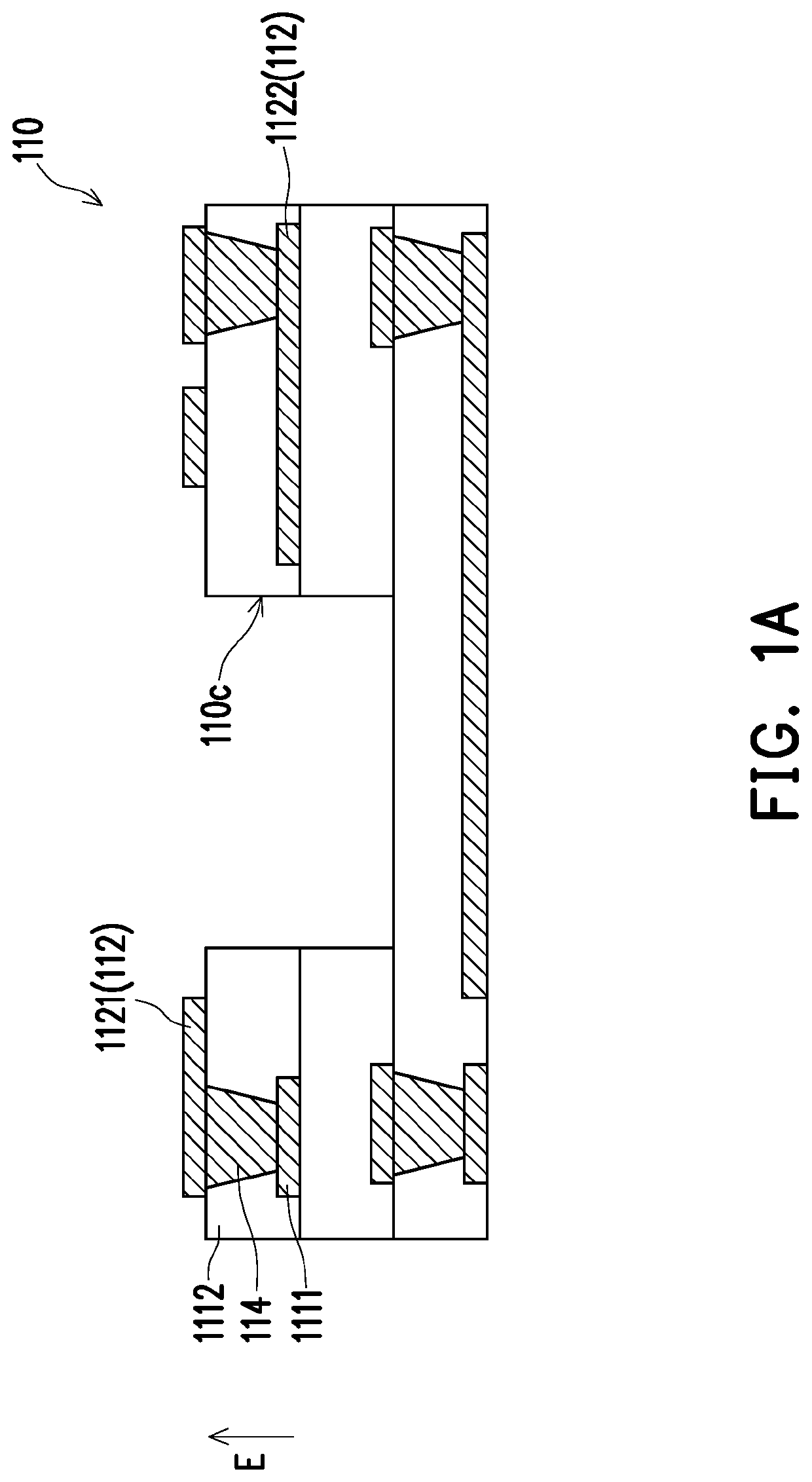
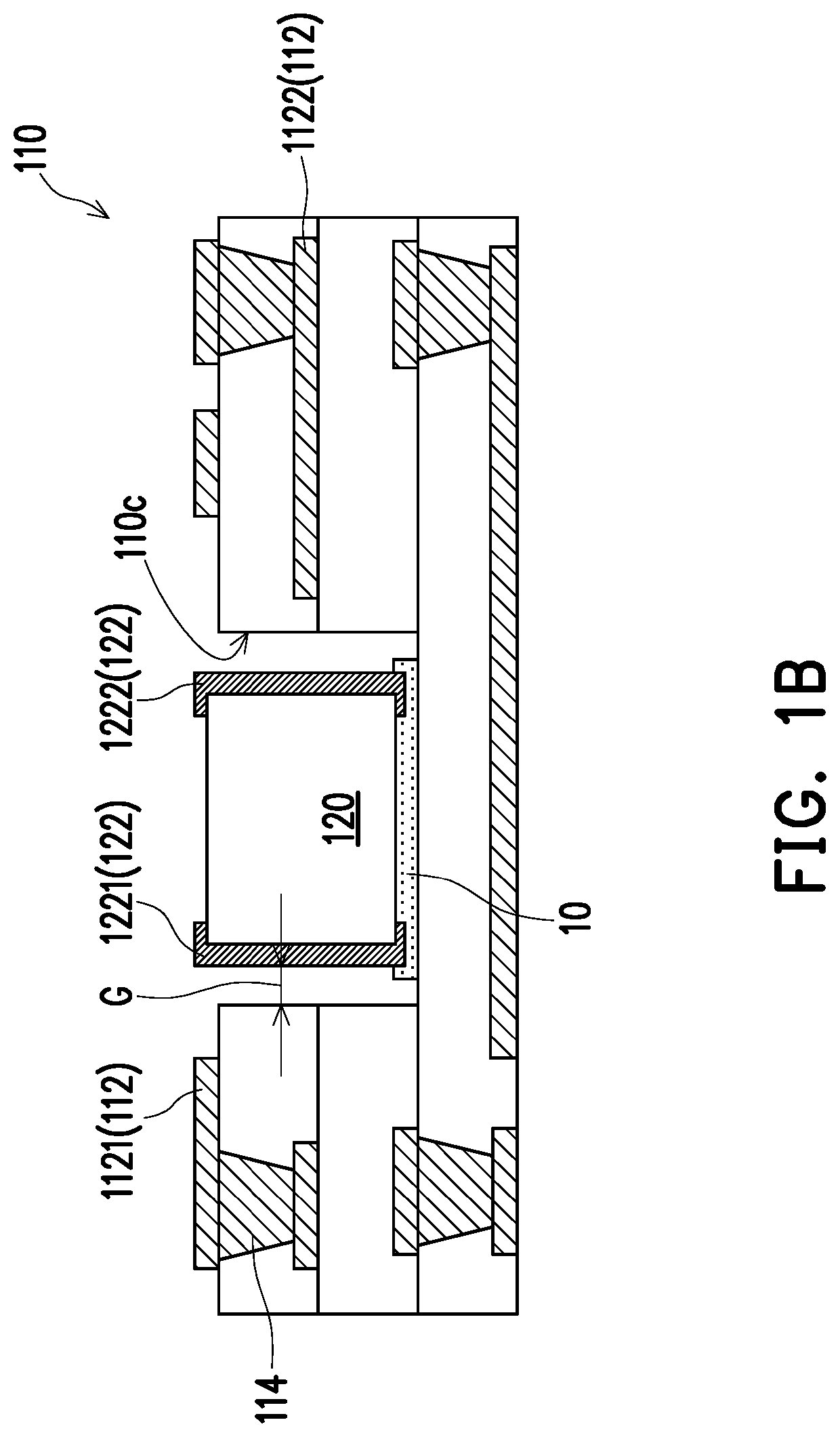
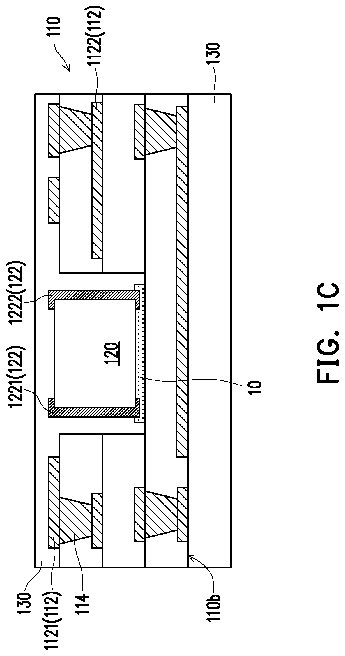
This patent describes an embedded component structure and a manufacturing method that can improve the quality, flexibility, yield, and reliability of electronic products. By improving the design of electrical connection positions in the electronic component, the conductive terminal can cover a part of the top surface and the side wall of the contacts, reducing redundant loss and improving quality. The embedded component structure can be connected to a circuit in various layers / directions, improving wiring flexibility on a three-dimensional structure. The manufacturing process prevents damage to the electronic component and improves yield and reliability.

Problems solved by technology

However, the electronic component configured on the circuit board may increase a carrying area.
In this way, excessive loss is easily generated, thereby reducing quality of the electronic product.

Method used


Image

  • Embedded component structure and manufacturing method thereof
  • Embedded component structure and manufacturing method thereof
  • Embedded component structure and manufacturing method thereof

Examples


Embodiment Construction

[0039]The foregoing and other technical content, features, and effects of the disclosure can be clearly presented below in detailed description with reference to embodiments of the accompanying drawings. The directional terms mentioned herein, like “above”, “below”, “front”, “back”, “left”, and “right”, refer to the directions in the accompanying drawings. Therefore, the directional terms are only used for illustration instead of limiting the disclosure.

[0040]In the detailed description of the embodiments, the terms, like “first”, “second”, and “third”, may be used for describing different elements. The terms are merely used for distinguishing between the elements, but these elements should not be limited by these terms in a structure. For example, a first element may be referred to as a second element, moreover, similarly, the second element may be referred to as the first element without departing from the protection scope of the ideas of the disclosure. In addition, in the manufa...


PUM


Abstract

An embedded component structure includes a circuit board, an electronic component, a first conductive terminal, and a second conductive terminal. The circuit board includes a first electrical connection layer and a second electrical connection layer. The electronic component is embedded in the circuit board and includes a first contact and a second contact. The first conductive terminal and the second conductive terminal respectively at least cover a part of top surfaces and side walls of the first contact and the second contact, and the first electrical connection layer and the second electrical connection layer are respectively electrically connected to the first contact and the second contact through the first conductive terminal and the second conductive terminal. A method for manufacturing an embedded component structure is also provided.

Description

CROSS-REFERENCE TO RELATED APPLICATION[0001]This application claims the priority benefit of Taiwan application serial no. 109123889, filed on Jul. 15, 2020. The entirety of the above-mentioned patent application is hereby incorporated by reference herein and made a part of this specification.BACKGROUND OF THE DISCLOSURE1. Field of the Disclosure[0002]The disclosure relates to an electronic component and a manufacturing method thereof, and in particular, to an embedded component structure and a manufacturing method thereof.2. Description of Related Art[0003]In recent years, an electronic component is usually carried by using a circuit board in an electronic product. However, the electronic component configured on the circuit board may increase a carrying area. Therefore, how to design an embedded component has become a current key technology. Furthermore, in a general embedded component, a position at which a contact is electrically connected is usually designed above or below the el...

Claims


Application Information

Patent Timeline
IPC IPC(8): H05K3/40H05K1/11H05K3/46H05K1/18
CPCH05K1/116H05K1/183H05K3/4038H05K3/4697H05K1/185H05K2203/1469H05K2201/10636H05K2201/09509Y02P70/50
Inventor CHEN, YU-SHENTSAI, I-TACHEN, CHIEN-CHIH
Owner UNIMICRON TECH CORP
Learn More