
Underwater traffic tunnel

a traffic tunnel and tunnel technology, applied in mining structures, artificial islands, construction, etc., can solve the problems of difficult structure of this type of bridge, complex seabed geological structure, and first sea-crossing bridge type that is difficult to construct, so as to achieve easy interaction with marine vessels, improve stability, and safe immersion

Active Publication Date: 2021-10-05
DU YANG
View PDF7 Cites 0 Cited by
  • Summary
  • Abstract
  • Description
  • Claims
  • Application Information

AI Technical Summary

Benefits of technology

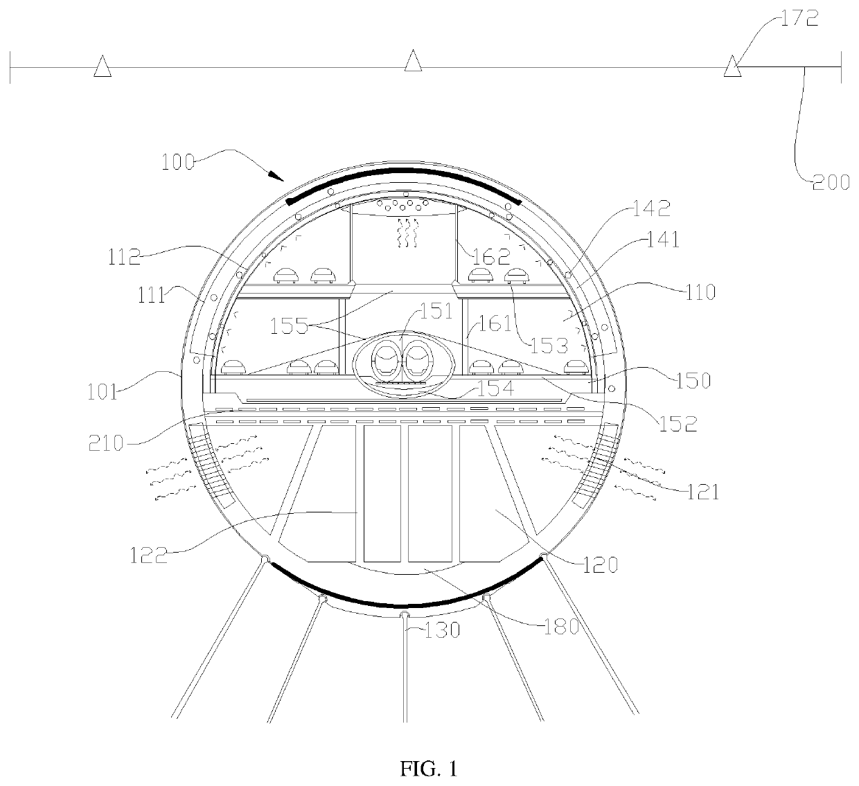
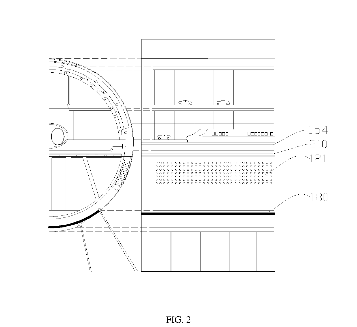
The present invention provides an underwater traffic tunnel that is safe and stable in water. It can navigate freely above the body and is not easy to interact with marine vessels. The tunnel has a second cavity that is in communication with water, which allows seawater to enter and play a certain counterweight role, preventing the body from overturning. Additionally, the ventilation system on the body can deform and move to prevent damage and impact by external forces. This guarantees that the traffic tunnel is safe, reduces the impact of changes in the earth crust such as earthquakes on the body of the tunnel, and has good ventilation guarantee.

Problems solved by technology

The first type of sea-crossing bridge is very difficult to construct.
Due to the changeable and severe environment of the sea, it is very difficult for the structure of this type of bridges to ensure safety and stability between two coasts with a large span.
However, it is completely built on the seabed and is greatly affected by crustal changes, seawater pressure, tsunamis, etc., and the seabed geological structure is complex.
Therefore, there is a greater risk for the construction of traffic bridges and tunnels on the seabed, and the stability and safety are poor; in addition, it is also difficult to solve safety issues such as ventilation problems and water ingress prevention.
However, the applicant found that although the above sea tunnel is not easily affected by crustal movement, and there is a part extending out of the sea surface, which affects the navigation of ships above the traffic tunnel to a certain extent.
In view of this, how to obtain a bridge and tunnel with a small impact on seaborne or waterborne ships and a stable structure has become an urgent problem to be solved.

Method used


Image

  • Underwater traffic tunnel
  • Underwater traffic tunnel
  • Underwater traffic tunnel

Examples


embodiment 1

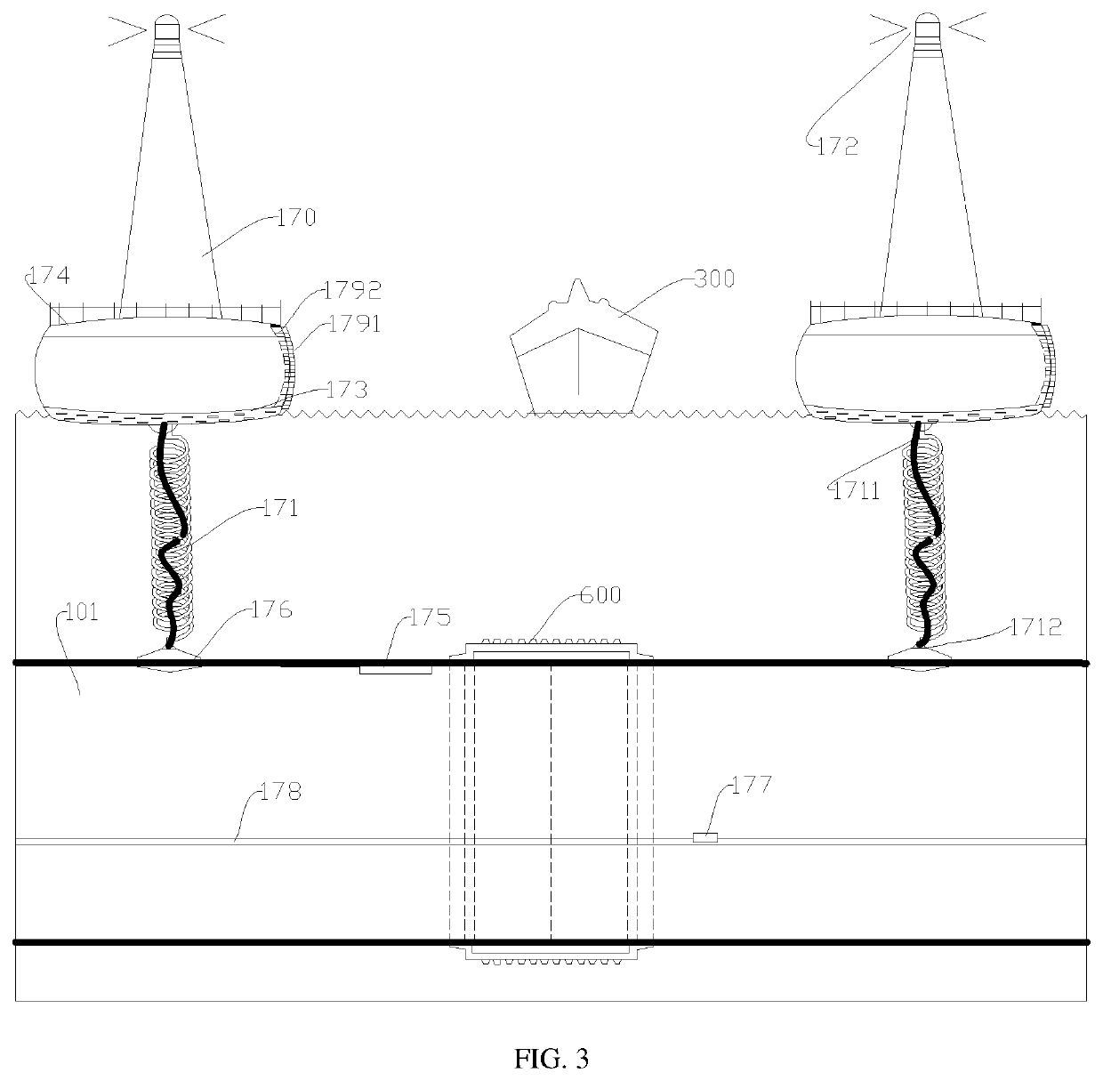
[0031]This embodiment provides a specific implementation of a ventilation system, which is deformable, and can buffer the impact of external force through deformation and ensure continuous ventilation at all times. As shown in FIG. 3, the ventilation system of this embodiment is provided at intervals along the extension direction of the body 101, and comprises a floating island 170 and a hose part 171 connecting the floating island 170 and the first cavity 110, wherein the floating island 170 is located above the water surface and is in the shape of a tower with an air port communicated with the hose part 171 on the upper part;

[0032]a water sealing valve 176 is provided between the bottom port of the hose part 171 and the first cavity 110, and the hose part 171 has a spiral shape to provide a deformation amount through expansion and contraction when impacted by an external force.

[0033]A limit part 1711 is further provided between the bottom of the floating island 170 and the body. T...

embodiment 2

[0043]This embodiment is an improvement made on the basis of the above embodiment 1. As shown in FIGS. 5 and 6, an escape system is provided on the body 101, and the escape system comprises a safety cabin 701 located outside the body 101 or inside the body 101 and an escape cabin 702 in the safe cabin 701;

[0044]the escape cabin 702 is provided with an aerobic space for accommodating people, and cabin doors provided on the sides and the top of the escape cabin are provided in the escape cabin 702, and a propeller propulsion system is configured on the escape cabin 702; a drainage structure 703 is provided in the safety cabin 701, and the drainage structure 703 is in communication with water.

[0045]The above structure can be a drainage pipe provided at the bottom of the safety cabin 701, the drainage pipe extends to water outside the body 101, and the drainage pipe and the safe cabin 701 are sealed by a water valve, which can be activated when drainage is required (the solenoid valve c...

embodiment 3

[0050]This embodiment is an improvement made on the basis of the above embodiment. In order to enable the underwater traffic tunnel to stably and safely connect the two established areas, the above steel cables, anchor rods 130, etc. are more suitable for being provided in the part of the body 101 in water. As shown in FIG. 8, in this embodiment, both ends of the body 101 close to the land are connected with a transition part, the transition part comprises a land-based section, an entrance and exit transition section and a sea-based section connected by a ring-shaped anchor 131 in turn from land to water, the sea-based section gradually descends to communicate with the body 101; in other words, the body 101 is gradually connected to the land through the transition part.

[0051]A support column 190 is provided at the bottom of the land-based section, an elastic connector is provided between the support column 190 and the body 101, the elastic connector may be a spring ring 191; here, t...


PUM


Abstract

An underwater traffic tunnel that includes a body immersed in water, a connector, and a ventilation system. The body comprises a first cavity for providing a passage space and a second cavity located below the first cavity. The second cavity is in communication with water; the connector connects the body and the water bottom and is used to resist buoyancy, and the ventilation system is in communication with the first cavity and extends above the water surface; the body of the present invention is safely immersed in water, and a vessel can navigate freely above the body; the second cavity is in communication with water and is not easy to be overturned by seawater; the connector resists buoyancy; the ventilation system can prevent damage by external forces through deformation and movement, and an escape system can be activated in emergency situations.

Description

CROSS REFERENCE TO RELATED APPLICATION[0001]This application claims the benefit of and takes priority from Chinese Patent Application Serial No. 202010738096.7 filed on Jul. 28, 2020, the contents of which are herein incorporated by reference.BACKGROUND OF THE INVENTIONField of the Invention[0002]The present invention relates to the technical field of traffic bridges and tunnels, in particular to an underwater traffic tunnel.Description of the Related Art[0003]Economic development has promoted the growth of traffic demand and accelerated the development of sea-crossing projects. At present, there are mainly two types of traffic buildings between two coasts with a great span: sea-crossing bridges and subsea tunnels.[0004]The applicant found that the prior art has at least the following technical problems:[0005]The first type of sea-crossing bridge is very difficult to construct. Generally, steel bars are driven deep into the ground, and then cement is poured to form piers, and finall...

Claims


Application Information

Patent Timeline
Patent Type & Authority Patents(United States)
IPC IPC(8): E21F1/00E02D29/067
CPCE02D29/067E21F1/003E02D29/063E02D27/52E02D27/525
Inventor DU, DI
Owner DU YANG
Learn More