Underwater traffic tunnel

A technology for tunnels and transportation, which is applied in mine/tunnel ventilation, water conservancy projects, underwater structures, etc., to achieve good ventilation, good stability, and reduced impact

Active Publication Date: 2020-11-03
杜同
View PDF8 Cites 9 Cited by
  • Summary
  • Abstract
  • Description
  • Claims
  • Application Information

AI Technical Summary

Problems solved by technology

[0008] The purpose of the present invention is to provide a traffic tunnel in water to solve the technical problem that the existing sea and seabed (underwater) and water traffic tunnels in the prior art are difficult to ensure structural stability under the premise of not interacting with passing ships; the present invention The many technical effects that can be produced by the preferred technical solutions among the many technical solutions provided are detailed below.

Method used


Image

  • Underwater traffic tunnel
  • Underwater traffic tunnel
  • Underwater traffic tunnel

Examples


Embodiment 1

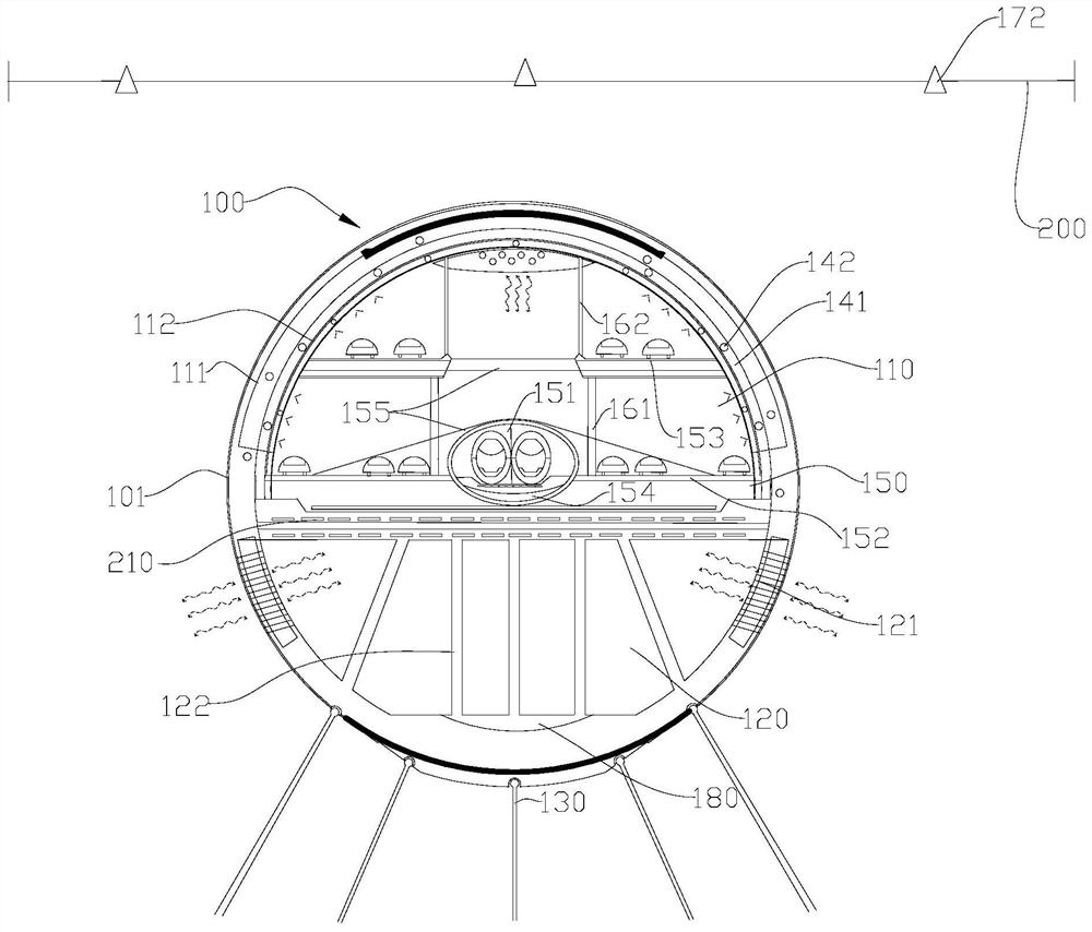
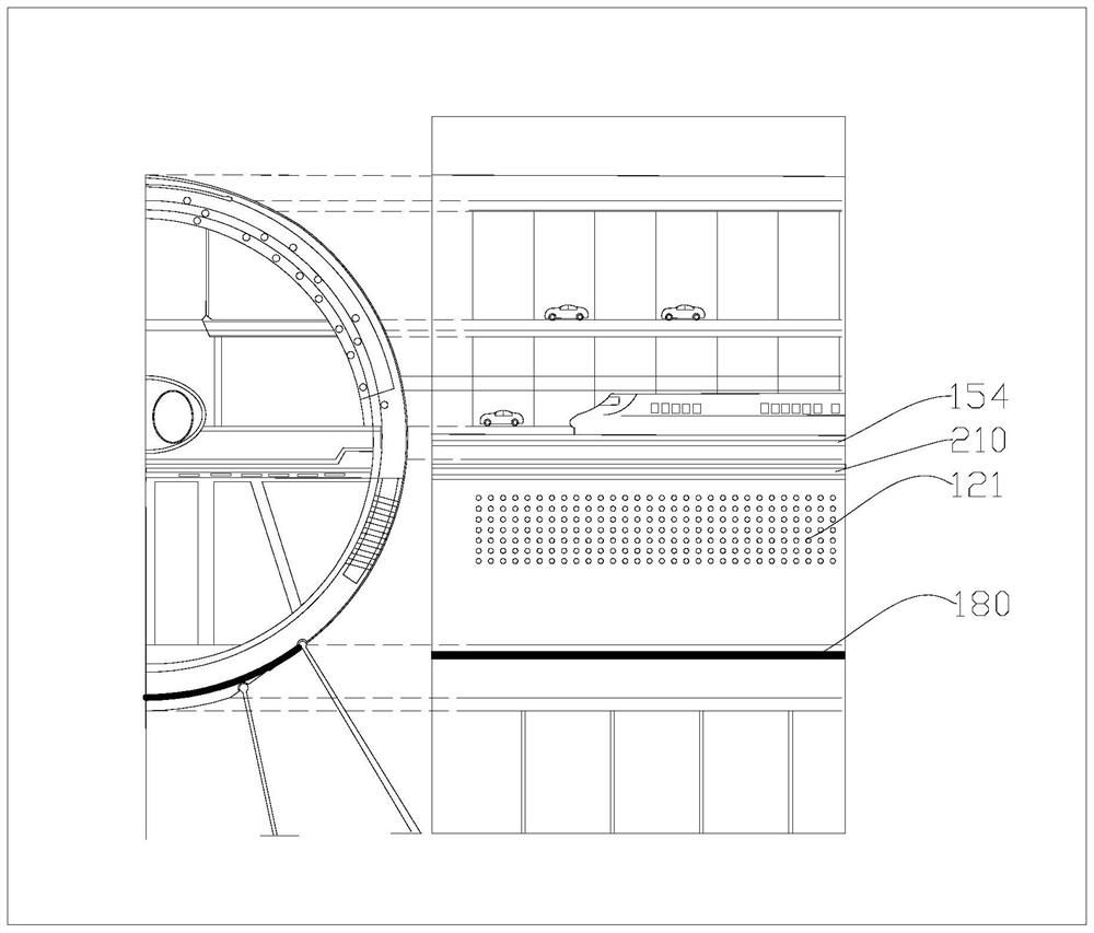
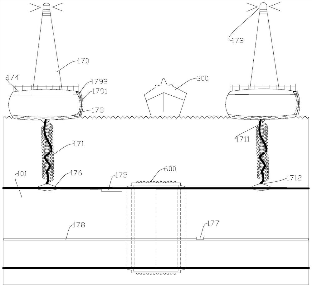
[0056] This embodiment provides a specific implementation of the ventilation system, which can be deformed, and the impact of external force can be buffered through deformation, so as to ensure continuous ventilation. see image 3 As shown, the ventilation system of this embodiment is arranged at intervals along the extending direction of the main body 101, which includes a floating island 170 and a hose portion 171 connecting the floating island 170 and the first cavity 110, wherein: the floating island 170 is located above the water surface and is in the shape of tower shape, there is an air port leading to the hose part 171 in its upper part;

[0057] There is a water sealing valve 176 between the bottom port of the hose part 171 and the first cavity 110 , and the hose part 171 is helical in order to provide deformation through expansion and contraction when subjected to an external force.

[0058] There is also a limiting part 1711 between the bottom of the floating islan...

Embodiment 2

[0069] This embodiment is an improvement on the basis of the above-mentioned embodiment 1, see Figure 5 and Figure 6 As shown, there is an escape system on the body 101, and the escape system includes a safety cabin 701 located outside the body 101 or inside the body 101, and an escape cabin 702 inside the safety cabin 701;

[0070] The escape cabin 702 is provided with an aerobic space for accommodating personnel, and there are hatches arranged on the side and the top of the escape cabin 702, and the escape cabin 702 is equipped with a propeller propulsion system; the safety cabin 701 is provided with a drainage structure 703 , the drainage structure 703 communicates with the water.

[0071] Wherein, the above-mentioned structure may be a drain pipe arranged at the bottom of the safety chamber 701, the drain pipe extends to the water outside the body 101, and the drain pipe and the safety chamber 701 are sealed by a water valve, which is activated when drainage is required...

Embodiment 3

[0077] This embodiment is an improvement made on the basis of the above-mentioned embodiments. In order to enable the underwater traffic tunnel to stably and safely connect two predetermined regions, the above-mentioned steel cables, anchor rods 130, etc. are more suitable for being arranged on the part of the main body 101 located in the water. . Such as Figure 8 As shown, in this embodiment, the two ends of the main body 101 close to the land are connected with a transition part, and the transition part from the land to the water sequentially includes a land-based section connected by an annular anchor 131, an entrance and exit transition section, and a sea-based section. The section gradually descends to communicate with the body 101; in other words, the body 101 gradually connects to the land through the transition part.

[0078] Wherein, there is a support column 190 at the bottom of the land-based section, and an elastic connector is arranged between the support column...


PUM


Abstract

The invention provides an underwater traffic tunnel, relates to the field of traffic bridges and tunnels, and solves the problem that offshore, in-water and underwater traffic tunnels are difficult toensure structural stability on the premise of not influencing passing ships. The underwater traffic tunnel comprises a body immersed in water, a connecting piece and a ventilation system, the body comprises a first cavity used for providing a passing space and a second cavity located at the lower portion of the first cavity, and the second cavity is communicated with the water; and the connectingpiece is connected with the body and the water bottom and used for resisting buoyancy, the ventilation system communicates with the first cavity and extends to the position above the water surface, and the ventilation system is arranged in a deformable manner so as to continuously ventilate when impacted. The body is safely immersed in water, and a ship can freely sail above the body; the secondcavity is communicated with water and is not easily overturned by seawater; the connecting piece resists buoyancy; and the ventilation system can be prevented from being damaged by external force through deformation movement, an escape system can be started in emergency, higher safety is achieved, and the influence of earth crust change on the tunnel is reduced.

Description

technical field [0001] The invention relates to the technical field of traffic bridges and tunnels, in particular to an underwater traffic tunnel. Background technique [0002] Economic development has promoted the growth of traffic demand and accelerated the development of cross-sea projects. At present, between the two coasts with large collapse, the traffic buildings mainly include two types: cross-sea bridges and subsea tunnels. [0003] The applicant finds that the prior art has at least the following technical problems: [0004] The construction of the first type of sea-crossing bridge is very difficult. Generally, steel bars are driven into the bed deep into the ground, then cement is poured to form bridge piers, and finally the bridge body on the sea is built. Due to the changeable and harsh environment of the sea, it is very difficult to ensure the safety and stability of the bridge structure between the two coasts with a large span. [0005] The second type of s...

Claims


Application Information

Patent Timeline
Patent Type & Authority Applications(China)
IPC IPC(8): E02D29/063
CPCE02D29/063E02D29/067E02D27/52E02D27/525E21F1/003
Inventor 杜地
Owner 杜同
Why Eureka
Try Eureka