Screw compressor

a compressor and screw technology, applied in the direction of machines/engines, rotary/oscillating piston pump components, liquid fuel engines, etc., can solve the problems of noise released from the casing, and achieve the effects of reducing the vibration of the main body, reducing the pressure fluctuation of the fluid, and reducing the noise generated

Active Publication Date: 2021-10-05
DAIKIN IND LTD
View PDF11 Cites 0 Cited by
  • Summary
  • Abstract
  • Description
  • Claims
  • Application Information

AI Technical Summary

Benefits of technology

[0018]According to the first aspect, the casing (10) is provided with the muffler space (50), reducing the pressure fluctuation of the fluid flowing into the high-pressure fluid passage (61, 64). Therefore, this can reduce vibration of the main body (10a) of the casing (10) due to the pressure fluctuation of the fluid, and further reduce noise generated due to the operation of the screw compressor (1).
[0019]In the third aspect, the screw compressor (1) includes two gate rotors (45, 46), and the screw rotor (40) is provided with odd number of helical grooves (41). Therefore, the waveforms of t

Problems solved by technology

If the fluid having a pressure that fluctuates relatively significantly passes through the high-pressure fluid passage,

Method used


Image

  • Screw compressor
  • Screw compressor
  • Screw compressor

Examples


first embodiment

Advantages of First Embodiment

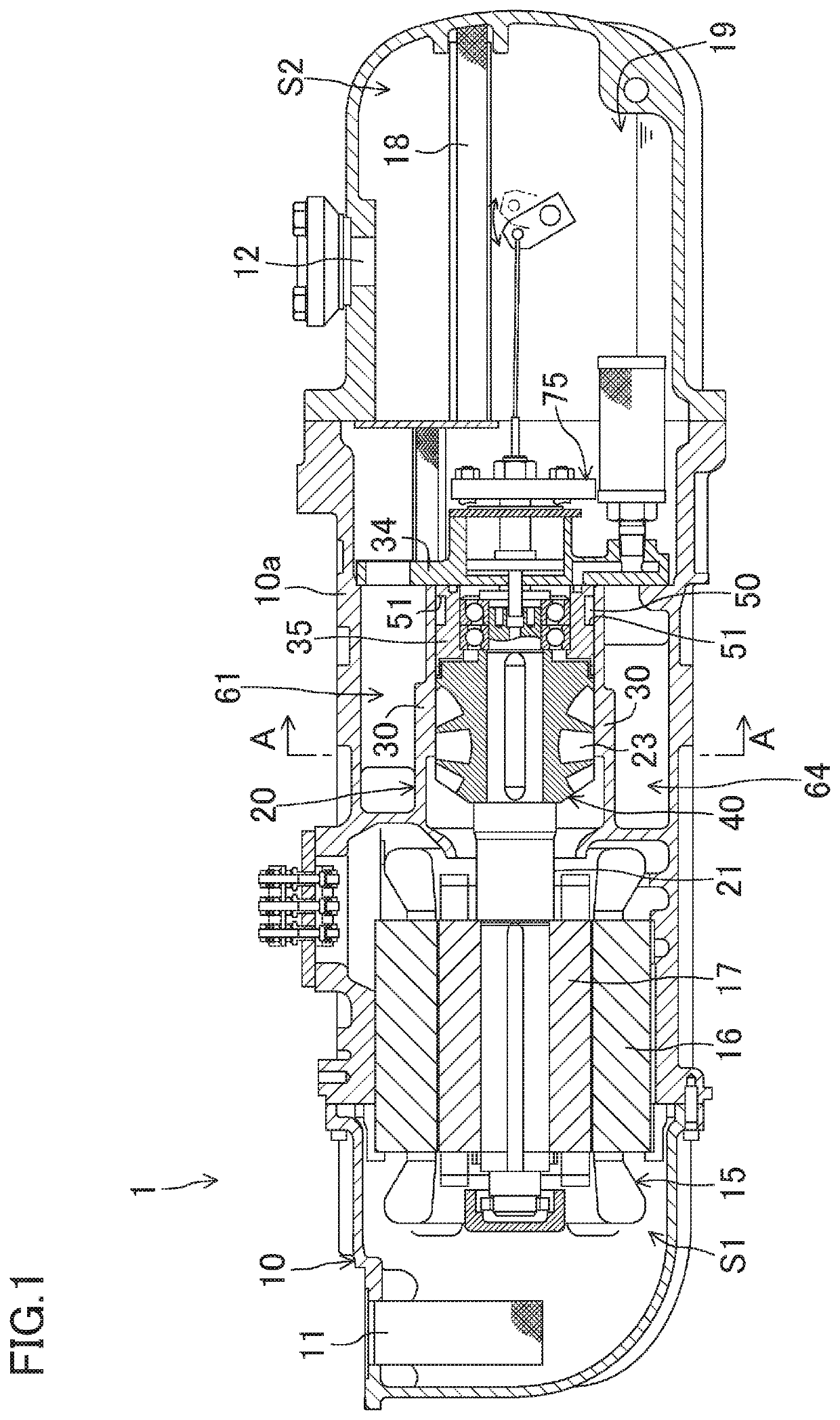
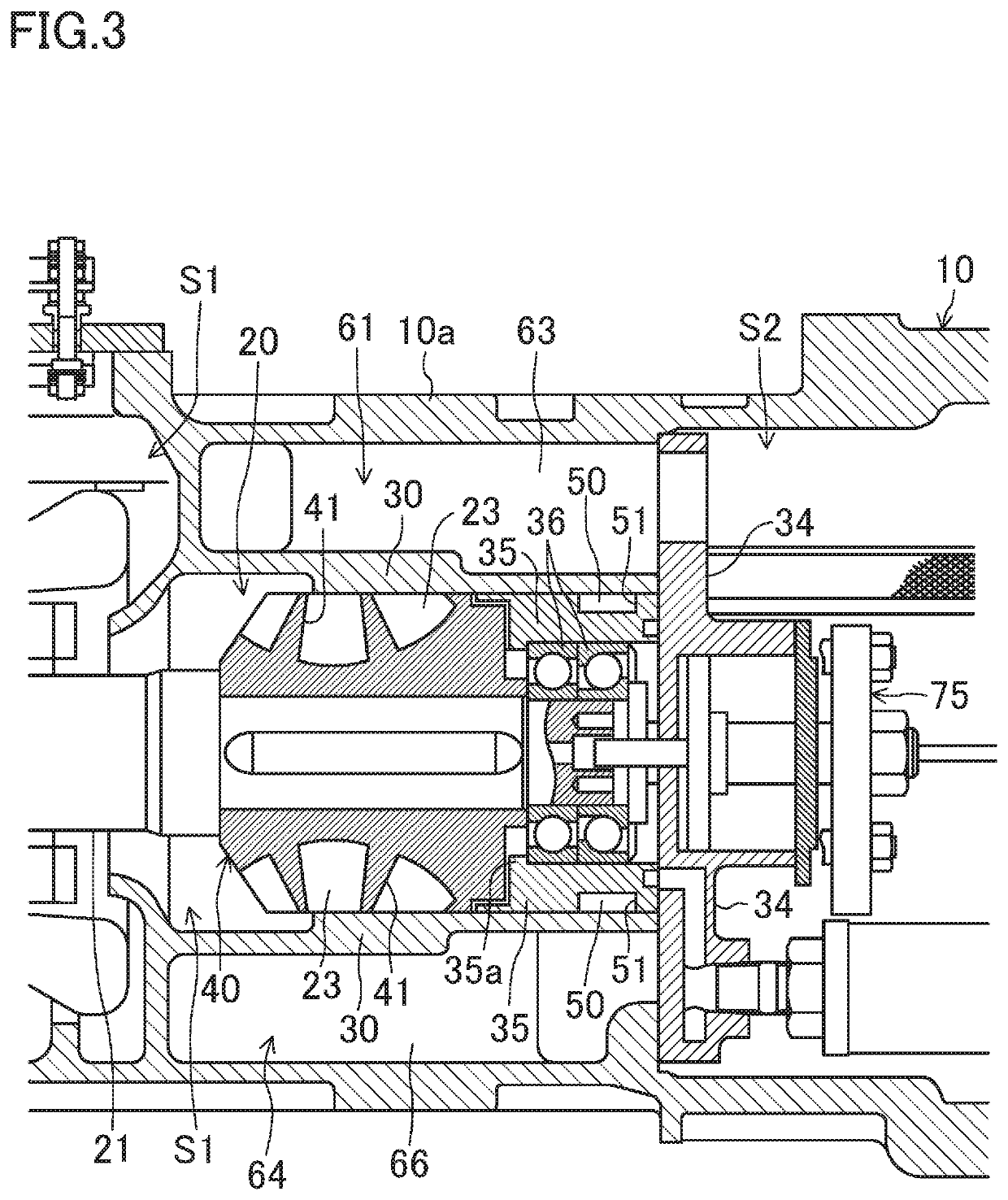
[0074]In the screw compressor (1) according this embodiment, the casing (10) is provided with the muffler space (50), thereby reducing the pressure fluctuations of the refrigerant flowing into the high-pressure fluid passages (61, 64). Therefore, this can reduce vibration of the main body (10a) of the casing (10) due to the pressure fluctuation of the refrigerant, and further reduce noise generated due to the operation of the screw compressor (1).

[0075]According to this embodiment, the screw compressor (1) is provided with the two gate rotors (45, 46), and the screw rotor (40) is provided with odd number of helical grooves (41). Therefore, the waveforms of the pressure fluctuations of the refrigerant in the first and second discharge passages (26, 27) are shifted from each other by a substantially half-wavelength. In this embodiment, the first discharge passage (26) and the second discharge passage (27) communicate with one muffler space (50). Therefore...

second embodiment

[0078]A second embodiment will be described. Here, it will be described how the screw compressor (1) in this embodiment is different from that in the first embodiment.

[0079]As illustrated in FIGS. 9 and 10, in the screw compressor (1) according to this embodiment, a recessed groove (52) is formed in the inner peripheral surface of the cylinder (30). This recessed groove (52) is a groove extending circumferentially along the inner peripheral surface of the cylinder (30), and faces the recessed groove (51) of the bearing holder (35). The width and the depth of the recessed groove (52) are constant over the entire length. The width of the recessed groove (52) of the cylinder (30) is substantially the same as that of the recessed groove (51) of the bearing holder (35). In the screw compressor (1) according to this embodiment, the recessed groove (51) of the bearing holder (35) and the recessed groove (52) of the cylinder (30) constitute the muffler space (50).

[0080]According to this emb...


PUM


Abstract

A screw compressor includes a casing, a screw rotor, a discharge passage, and at least one muffler space. The casing includes a cylindrically-shaped cylinder, a main body surrounding a vicinity of the cylinder, and a high-pressure fluid passage provided between the main body and the cylinder. The screw rotor includes a plurality of helical grooves. The screw rotor is inserted into the cylinder to define fluid chambers. A fluid is sucked into the fluid chambers to compress the fluid. The discharge passage is disposed in the casing. The discharge passage guides the fluid that has been discharged from the fluid chambers to the high-pressure fluid passage. The at least one muffler space is disposed in the casing. The at least one muffler space communicates with the discharge passage so as to reduce a pressure fluctuation of the fluid flowing from the discharge passage to the high-pressure fluid passage.

Description

CROSS-REFERENCE TO RELATED APPLICATIONS[0001]This U.S. National stage application claims priority under 35 U.S.C. §119(a) to Japanese Patent Application No. 2016-117678, filed in Japan on June 14, 2016, the entire contents of which are hereby incorporated herein by reference.TECHNICAL FIELD[0002]The present invention relates to a screw compressor for compressing a fluid.BACKGROUND ART[0003]Screw compressors have been used as a compressor for compressing a fluid. For example, Japenese Unexamined Patent Publication No. 2001-065481 discloses a single-screw compressor having one screw rotor and two gate rotors.[0004]In the screw compressor disclosed in Japenese Unexamined Patent Publication No. 2001-065481 the screw rotor and the gate rotors are housed in a casing. The screw rotor is inserted into a cylinder formed in the casing. The cylinder is surrounded by a main body of the casing. The screw rotor has a plurality of helical grooves, and the helical grooves define fluid chambers. The...

Claims


Application Information

Patent Timeline
IPC IPC(8): F04C29/06F04C18/52F01C21/02F16C19/14
CPCF04C29/065F04C18/52F04C29/068F01C21/02F04C2240/45F04C2240/56F16C19/14F04C29/06F05B2260/964F04C18/16
Inventor UENO, HIROMICHI
Owner DAIKIN IND LTD
Why Eureka
Try Eureka