Cooling structure for coil component

a technology of cooling structure and coil, which is applied in the direction of transformers/inductance details, transformers, electrical devices, etc., can solve the problems of difficulty in uniformly and sufficiently cooling coils, and achieve the effect of efficient and uniform cooling of an entire coil and reducing the total size and cost of the devi

Active Publication Date: 2021-10-05
FUJI ELECTRIC CO LTD
View PDF9 Cites 0 Cited by
  • Summary
  • Abstract
  • Description
  • Claims
  • Application Information

AI Technical Summary

Benefits of technology

[0020]The present invention makes it possible to efficiently and uniformly cool an entire coiled component by attaching a flow-rectifying member having flow-rectifying ribs to the coiled component in order to form a first cooling air channel around the coils, the cooling air then being passed through this channel.
[0021]This allows the capacity of a cooling device, such as a cooling fan, to be small, which makes it possible to reduce the total size and cost of a device having coil units embedded therein.

Problems solved by technology

Accordingly, in the conventional technology, it was difficult to uniformly and sufficiently cool the coils 102&103 and the core structure 101.

Method used


Image

  • Cooling structure for coil component
  • Cooling structure for coil component
  • Cooling structure for coil component

Examples


Embodiment Construction

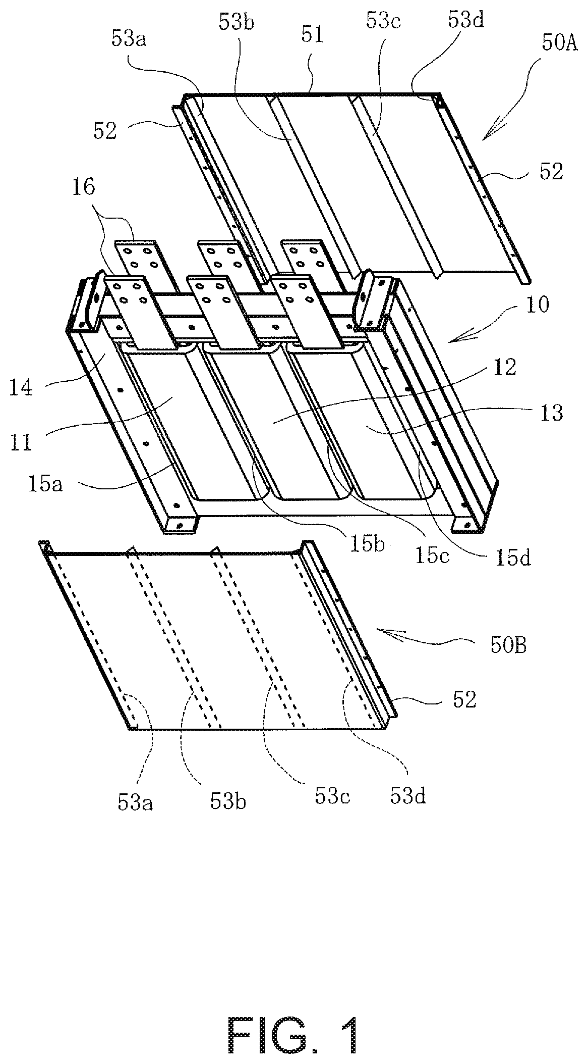
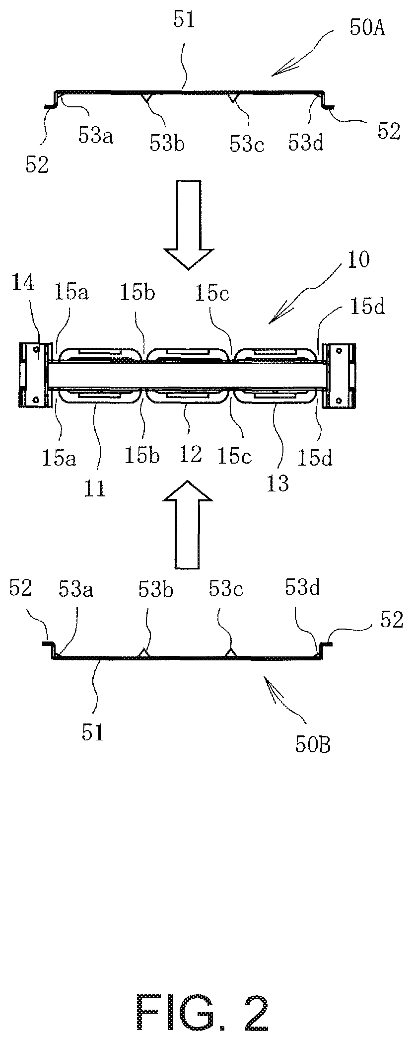
[0029]An embodiment of the present invention will be explained below with reference to the drawings. This embodiment is the present invention as applied to a shell-type reactor, which is a coil unit; FIG. 1 is an exploded perspective view of the reactor, and FIG. 2 is a plan view of the assembly state.

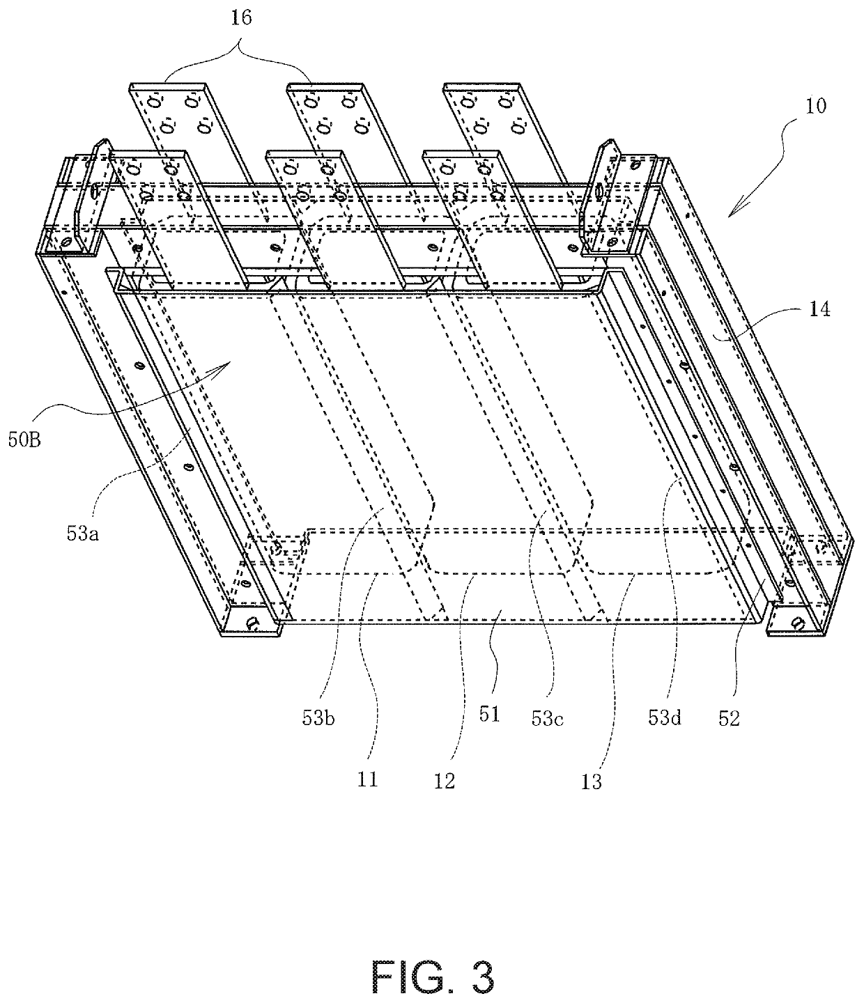
[0030]In FIGS. 1 and 2, reference number 10 is the shell-type reactor, which is the coil unit of a coil device, and this shell-type reactor has three phase coils 11, 12, and 13 and a core structure 14 in which these coils 11, 12, and 13 are wound. The core structure 14 of the coil device has three leg parts respectively disposed in the centers of the coils 11, 12, and 13, and two leg parts disposed outside the coils 11 and 13.

[0031]Reference number 16 is an output conductor for connecting the coils 11, 12, and 13 to an external conductor (not shown).

[0032]Furthermore, reference numbers 50A and 50B are flow-rectifying members attached from both sides of the coils 11, 12, and 13 so as to...


PUM

PropertyMeasurementUnit
core structureaaaaaaaaaa
lengthaaaaaaaaaa
shapeaaaaaaaaaa

Abstract

A coil device with a cooling structure includes: a coil unit that has a core structure having one or more leg parts and one or more coils wound around the one or more leg parts; and a flow-rectifying member having a flat plate portion covering a face of the one or more coils and flow-rectifying ribs inwardly protruding from an inner surface of the flat plate portion, the flow-rectifying ribs extending in a direction parallel to center axes of the one or more coils and being positioned to face side boundaries of the face of the one or more coils. The flat plate portion and the flow-rectifying ribs form a first air cooling channel at a substantially uniform gap outside of the one or more coils along the direction parallel to the center axes thereof, the first air cooling channel passing cooling air to air-cool the one or more coils.

Description

BACKGROUND OF THE INVENTIONTechnical Field[0001]The present invention relates to a cooling structure for air cooling coil units such as transformers or reactors.Background Art[0002]FIGS. 5A to 5C show a core-type reactor described in Patent Document 1: FIG. 5A is a plan view, FIG. 5B is a front view, and FIG. 5C is a right side view.[0003]In these drawings, reference number 101 is the core structure, and coils 102 and 103 are wound around the pair of leg parts of the core structure. A flow-rectifying member 104 made of an insulating material is also disposed so as to surround a portion of the coils 102 and 103 in the axial direction.[0004]FIG. 6 is a plan view for describing the cooling effects of this conventional technology. Reference numbers 101a and 101b indicate magnetic gaps formed in the core structure 101.[0005]In FIG. 6, when a high-frequency current flows to the coils 102 and 103, not only does the temperature of the coils 102 and 103 increase, but so does the temperature ...

Claims


Application Information

Patent Timeline
Patent Type & Authority Patents(United States)
IPC IPC(8): H01F27/08H01F27/28H01F30/12
CPCH01F27/085H01F27/28H01F27/2876H01F30/12
Inventor TAKAHASHI, KIYOSHI
Owner FUJI ELECTRIC CO LTD
Why Eureka
Try Eureka