Configuration of coolable turbine blade

A technology for turbine blades and cooling fluids, applied in the direction of blade support elements, engine functions, mechanical equipment, etc., can solve problems such as geometric structure restrictions, trailing edge overheating, etc., and achieve a soft transition effect

Inactive Publication Date: 2006-11-08
SIEMENS AG
View PDF0 Cites 0 Cited by
  • Summary
  • Abstract
  • Description
  • Claims
  • Application Information

AI Technical Summary

Problems solved by technology

The result is overheating of the trailing edge
In addition, the geometry of the turbine blades, which are often large

Method used


Image

  • Configuration of coolable turbine blade
  • Configuration of coolable turbine blade
  • Configuration of coolable turbine blade

Examples


Embodiment Construction

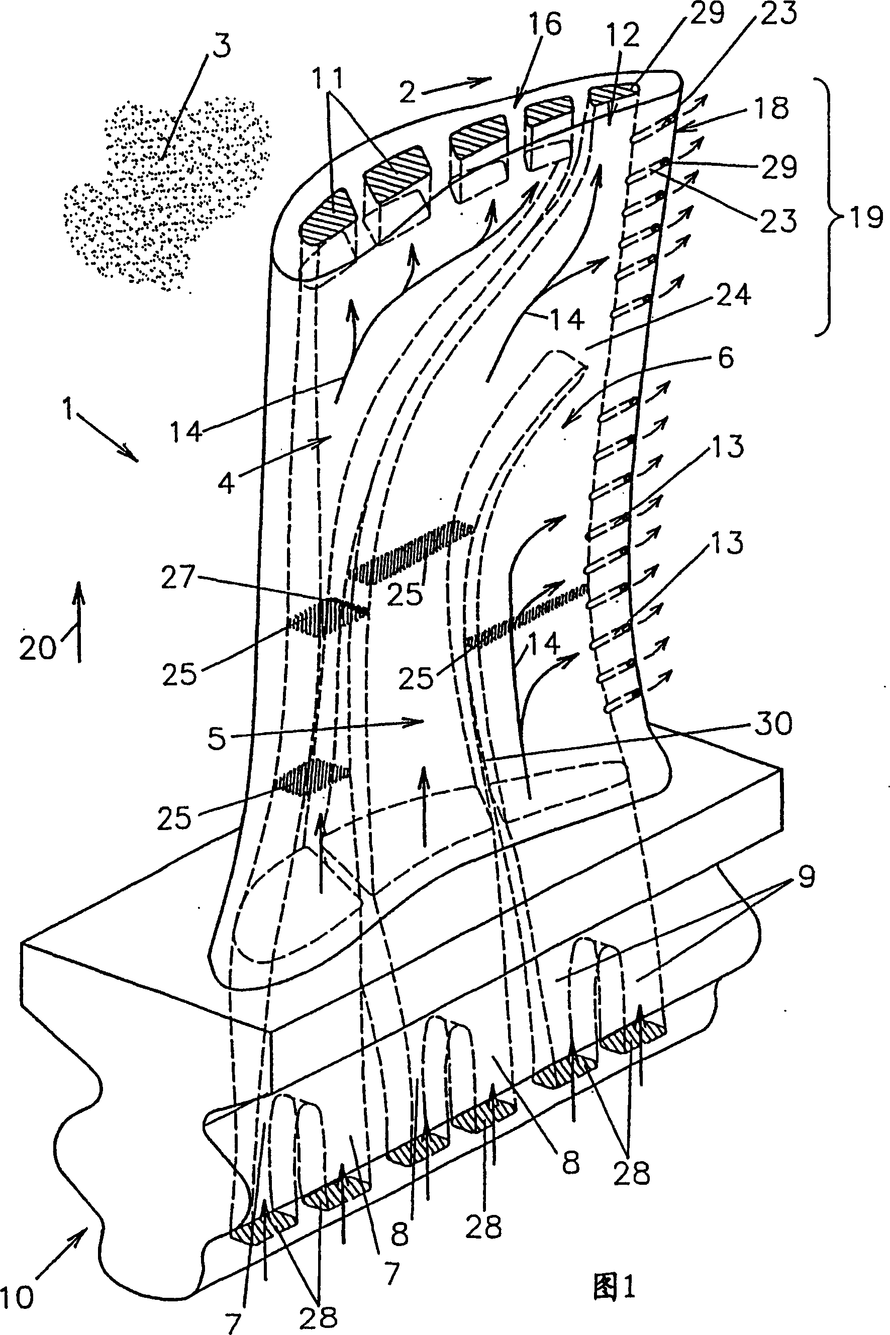
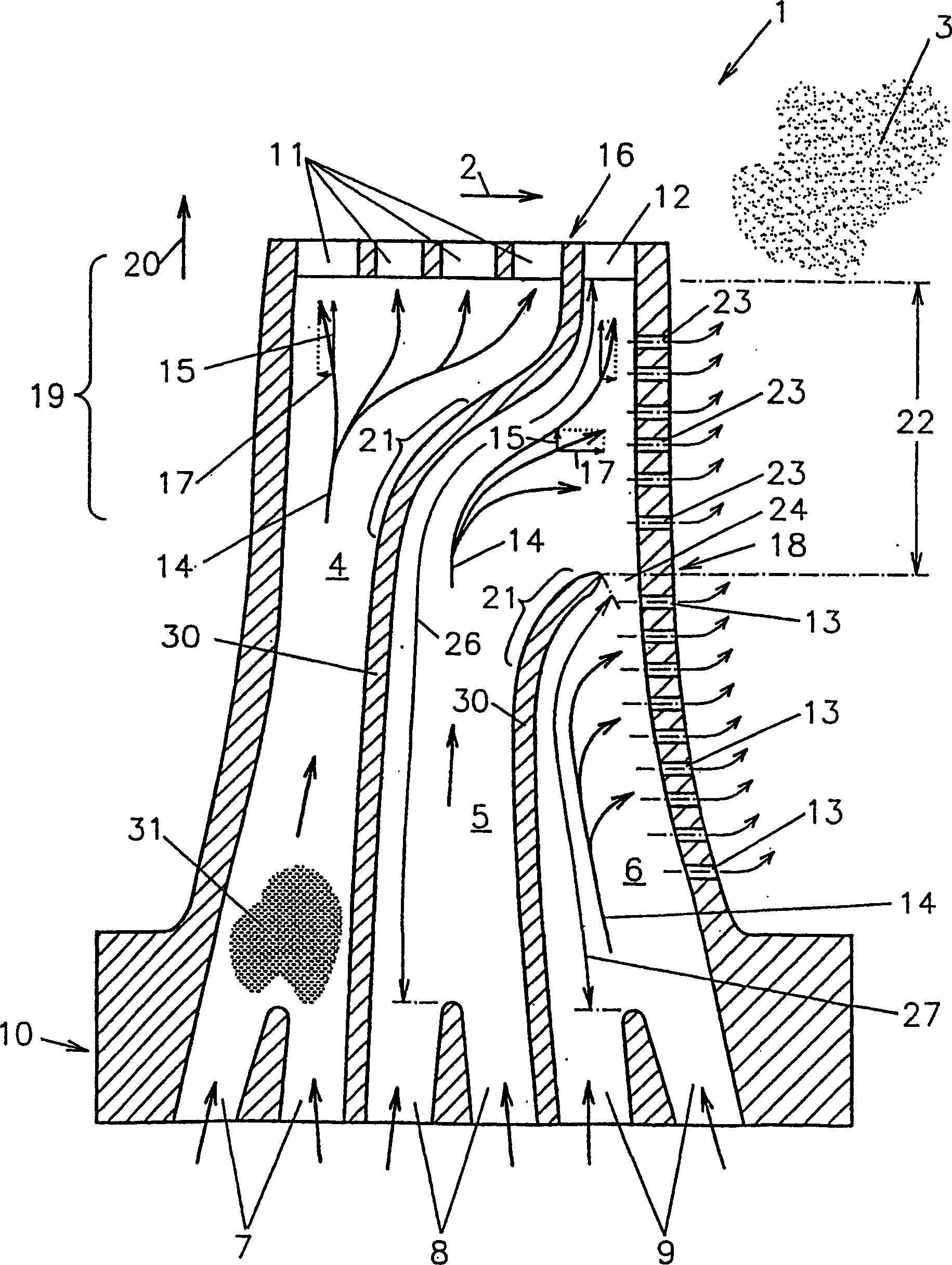
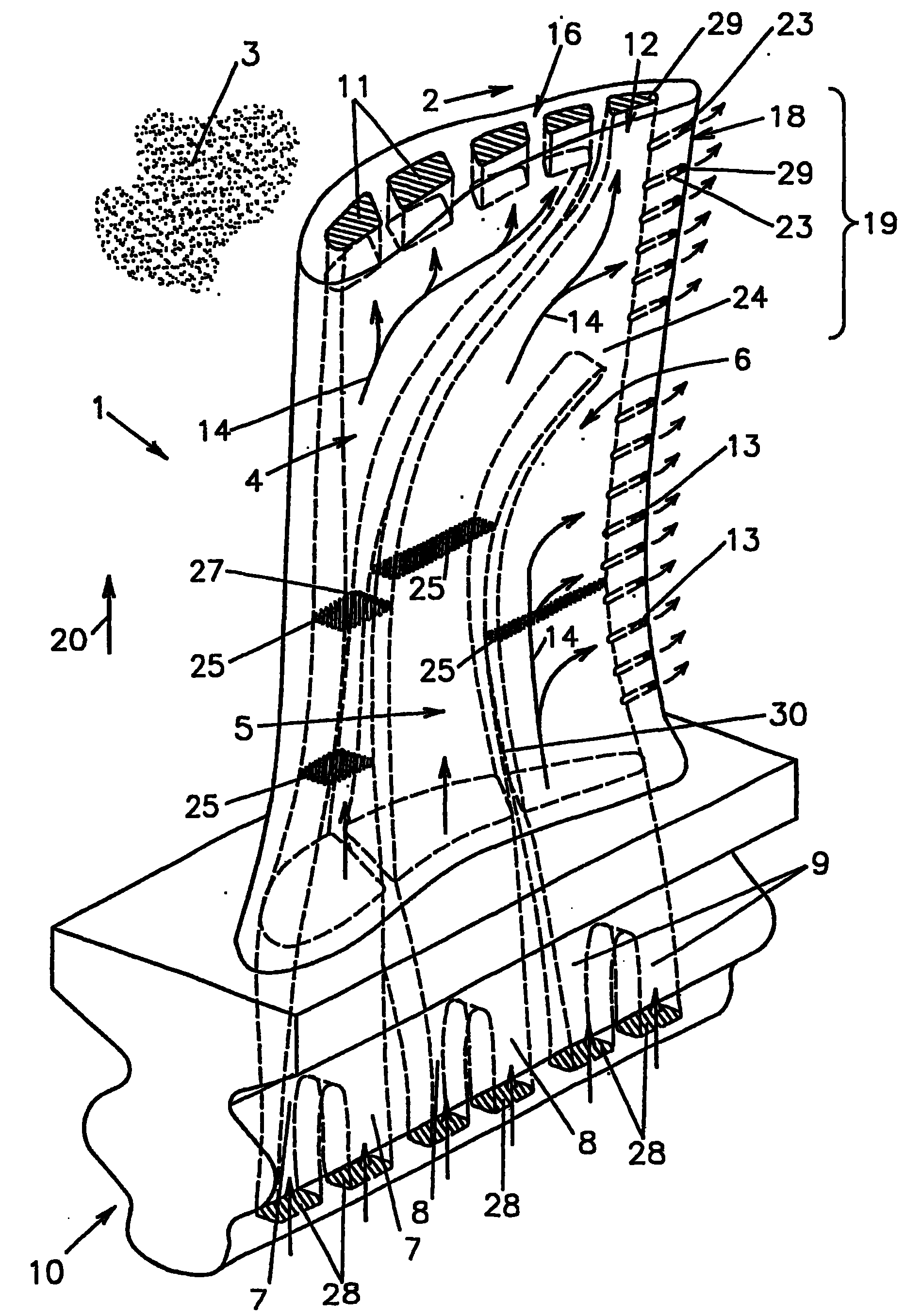
[0029] The turbine blades 1 are surrounded by a working fluid 3 (only a part of which is shown as an example in FIG. 1 ) in the outflow direction 2 , thereby producing work and driving the turbine. Turbine blade 1 is cooled by fluid 31 (the cooling fluid is in figure 2 , likewise only partly shown as an example), flow along the flow channels 4 , 5 , 6 . This cools the turbine blade 1 . The cooling fluid 31 can be (cooling) air, for example.

[0030]The turbine blade 1 has a blade root 10 which is inserted into a corresponding groove on the turbine disk (not shown in the figure) and fixed there. The inflow holes 7, 8, 9 are shown in alignment with corresponding holes in the turbine wheel. The cooling fluid 31 is fed into the flow channels 4 , 5 , 6 through them.

[0031] The flow channels 4 , 5 , 6 are between the inflow holes 7 , 8 , 9 at the radially inner blade root 10 and the radially outer outlet holes 11 , 12 , 13 opposite the blade root 10 extend. This extension ha...


PUM


Abstract

The invention relates to a turbine blade (1) through which a cooling fluid flows, which has a plurality of flow channels (4, 5, 6) arranged adjacently along the outflow direction (2) of a working fluid (3), the flow Inlet holes (7, 8, 9) of channels (4, 5, 6) at the radially inner blade root (10) and outlet holes (11 , 12, 13) extend in such a way that the radial flow component (15) of the resultant cooling fluid flow (14) is practically oriented mainly radially outwards, wherein there is a (2) Look at the flow channel (4) at the front, whose outflow hole (11) is machined in the brushing edge (16) of the turbine blade (1). In addition, at least one trailing channel (5, 6) is provided, in which the combined cooling fluid flow (14) additionally has a local transverse flow component (17), and the outflow holes (12, 13) of the trailing channel Machined in the trailing edge (18) of the turbine blade (1).

Description

technical field [0001] The invention relates to a turbine blade through which a cooling fluid flows. Background technique [0002] Such turbine blades, through which a cooling fluid flows, have inner flow channels which are separated from one another by inner walls. The turbine blades are surrounded by the working fluid. Such turbine blades are, for example, turbine blades of a gas turbine, and the working fluid is correspondingly gas. The turbine blades are inclined relative to the inflowing working fluid, so a component force is usually formed along the circumference of the turbine. The outflow direction of the working fluid is therefore essentially the direction in which the working fluid flows around the turbine blades. [0003] Turbine blades of the above-mentioned type are turbine blades which are installed in the rear section of the turbine. There the working fluid is expanded and cooled to such an extent that only a small amount of cooling of the turbine blades i...

Claims


Application Information

Patent Timeline
IPC IPC(8): F01D5/18
CPCF01D5/187B22C9/10F05D2260/20F05D2260/22141
Inventor 彼得·蒂曼迈克尔·斯特拉斯伯格
Owner SIEMENS AG
Why Eureka
Try Eureka