
Method of preoperative planning to correct spine misalignment of a patient

a patient and preoperative planning technology, applied in the field of patient preoperative planning to correct spine misalignment, to achieve the effect of quick and efficient convergence of thoracic kyphosis

Active Publication Date: 2021-10-12
EOS IMAGING
View PDF215 Cites 3 Cited by
  • Summary
  • Abstract
  • Description
  • Claims
  • Application Information

AI Technical Summary

Benefits of technology

The invention aims to provide a better way to plan surgery to correct spine misalignment by creating a more precise model of the spine based on the patient's parameters. The model takes into account both the curvature of the spine and the position of the spine in relation to the patient's body. This helps to create a map that is more accurate and that can help guide the surgery to correct the spine's misalignment. The method involves simultaneously translating and rotating the imaged vertebral portions in both the coronal and sagittal planes. The model is then adapted based on the patient's parameters to better match the natural curvatures of the spine. This flexibility allows for quicker and more efficient convergence of the spine's misalignment.

Problems solved by technology

Unfortunately, in this prior art, the translation and rotation performed in the sagittal plane lead to an associated pre-twisted rod to be integrated within a patient body to support a patient spine, which has been pre-twisted recording to position and orientation of a set of imaged vertebrae after a step of making a translation and a rotation in a sagittal plane performed during such a method of preoperative planning to correct spine misalignment of a patient which lacks precision as to its length and as to its curvature location.

Method used


Image

  • Method of preoperative planning to correct spine misalignment of a patient
  • Method of preoperative planning to correct spine misalignment of a patient
  • Method of preoperative planning to correct spine misalignment of a patient

Examples


Embodiment Construction

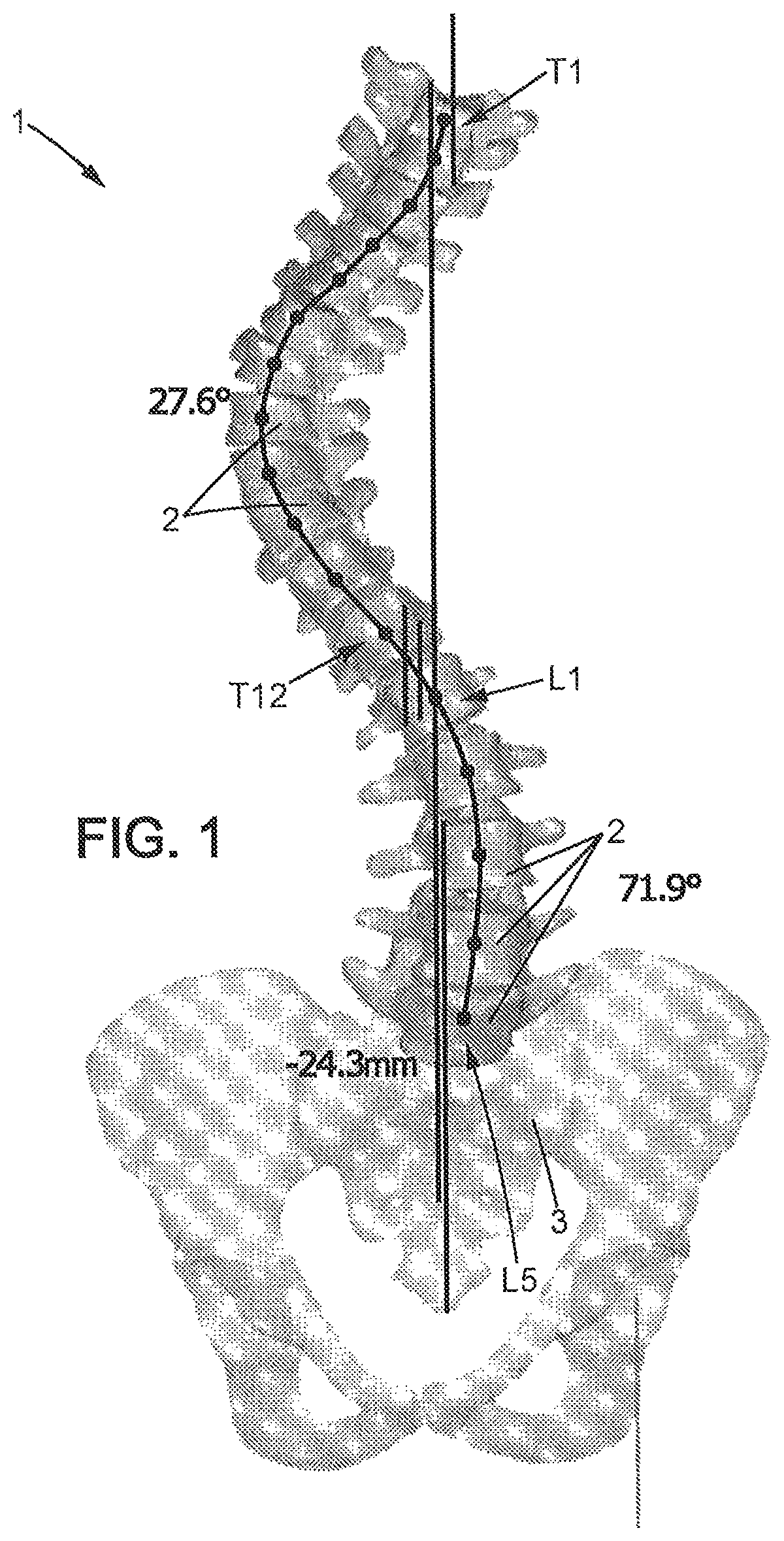
[0048]FIG. 1 shows a frontal patient spine view, the patient suffering from scoliosis, allowing performance of a step of the method of preoperative planning according to an embodiment of the invention.

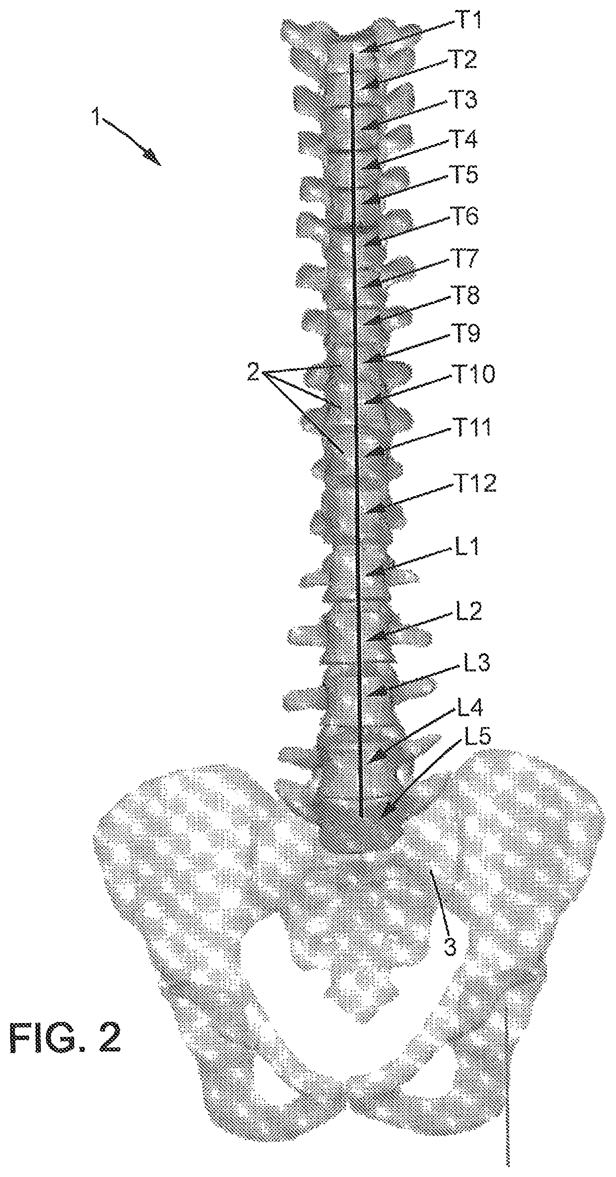
[0049]A patient spine 1 comprises vertebrae 2 and is ended by pelvis 3. Vertebrae 2 comprise thoracic vertebrae T1 to T12 and lumbar vertebrae L1 to L5. A sane spine 1 should appear as vertical in the coronal plan. Here, one can see that the spine 1 is heavily curved toward left of FIG. 1 in its upper part, corresponding to thoracic vertebrae 2, and slightly curved toward right of FIG. 1 in its lower part, corresponding to lumbar vertebrae 2. This means that represented spine 1 suffers from a disease called scoliosis. This means that represented spine 1 should be made straight in coronal plan. Therefore, imaged thoracic vertebrae T1 to T12 should be moved to the right of FIG. 1, whereas imaged lumbar vertebrae L1 to L5 should be moved to the left of FIG. 1.

[0050]FIG. 2 shows a frontal ...


PUM


Abstract

This invention relates to a method of preoperative planning to correct spine misalignment of a patient, comprising a step of making a translation and a rotation, in a sagittal plane, of each vertebra of a set of several cervical and / or thoracic and / or lumbar imaged spine vertebrae, so that said set of imaged vertebrae presents afterwards, in the sagittal plane, the same cervical lordosis and / or the same thoracic kyphosis and / or the same lumbar lordosis as a model adapted for said patient, wherein it also comprises, before said step of making said translation and said rotation in a sagittal plane: a step of making a translation and a rotation, in a coronal plane, of each vertebra of said set of several cervical and / or thoracic and / or lumbar imaged spine vertebrae, so that said set of imaged vertebrae becomes straight in said coronal plane, and of making a rotation, in an axial plane, of each vertebra of said set of several cervical and / or thoracic and / or lumbar imaged spine vertebrae, so that said set of imaged vertebrae becomes axially aligned.

Description

CROSS-REFERENCE TO RELATED APPLICATION[0001]This Application is a 35 USC § 371 US National Stage filing of International Application No. PCT / IB2015 / 002497 filed on Nov. 19, 2015.FIELD OF THE DISCLOSURE [0002]The invention relates to a method of preoperative planning to correct spine misalignment of a patient and to the associated pre-shaped or pre-twisted rod, to be integrated within a patient body to support a patient spine, which has been pre-shaped or pre-twisted according to position and orientation of a set of imaged vertebrae after a step of making a translation and a rotation in a sagittal plane performed during such a method of preoperative planning to correct spine misalignment of a patient.BACKGROUND OF THE DISCLOSURE[0003]According to a prior art, it is known a method of preoperative planning to correct spine misalignment of a patient based on a step of making a translation and a rotation, in a sagittal plane, of each vertebra of a set of several cervical and / or thoracic ...

Claims


Application Information

Patent Timeline
Patent Type & Authority Patents(United States)
IPC IPC(8): A61B17/70A61B34/10A61B6/00
CPCA61B34/10A61B6/505A61B6/5217A61B17/7011A61B17/7013A61B2034/102A61B2034/105A61B2090/367
Inventor HOBEIKA, JOEVANCURA, LUKAS
Owner EOS IMAGING
Learn More