
Improvements in or relating to variable focusing power optical devices

a technology of optical devices and variable focusing power, applied in the field of variable focusing power optical devices, can solve the problems of difficult in practice, inability to achieve fast cooling and high force of wires, and the need to create an adjustable lens with good optics, etc., to improve the optics and hence the experience of users. , the effect of high for

Pending Publication Date: 2021-02-04
ADLENS
View PDF6 Cites 27 Cited by
  • Summary
  • Abstract
  • Description
  • Claims
  • Application Information

AI Technical Summary

Benefits of technology

The patent describes a device that uses shape memory alloy wires to control the shape of a fluid-filled lens. This technology allows for precise actuation of the lens at different points, improving its optics and user experience. The device can make use of a pulse-width-modulated voltage to transform the shape of the wires, and can involve using an electronic bus to supply voltage to the wires. The invention also allows for control of individual sections of the wire array, providing flexibility in adjusting the length of the wires. Overall, the technology enables greater control over the non-standard shape of a fluid-filled lens, leading to improved performance and a better user experience.

Problems solved by technology

Whilst the lens or mirror assembly of WO 2013 / 144592 A1 achieves acceptable results, an ongoing problem associated with liquid lenses, particularly non-round lenses, is the need to create an adjustable lens with good optics.
This may be difficult in practice, however.
Three major limitations on SMA wires as actuators are:i) the maximum useable actuation force and cooling time of a wire both go as the square of the wire diameter (for instance data from the Dynalloy® website), so that a wire cannot be both fast cooling and high force;ii) the actuation distance is typically only 3% of the wire's length; andiii) the wire is a two-state actuator.

Method used


Image

  • Improvements in or relating to variable focusing power optical devices
  • Improvements in or relating to variable focusing power optical devices
  • Improvements in or relating to variable focusing power optical devices

Examples


example 1

Fluid Filled Lens with Three Active Control Points

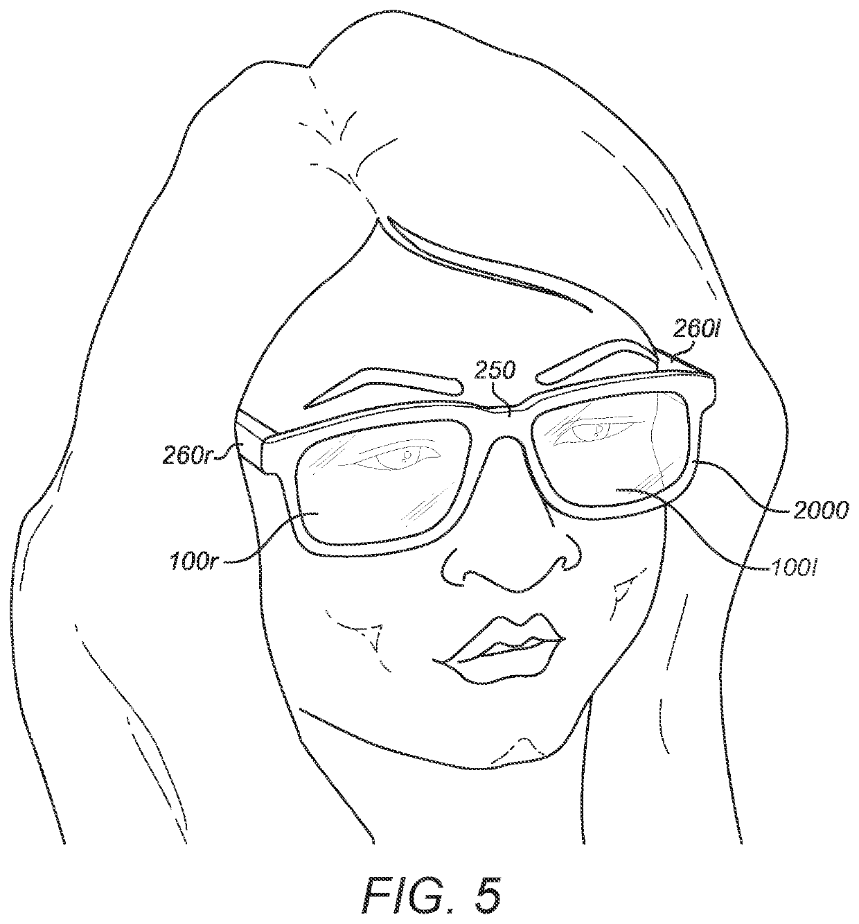
[0079]FIG. 5 shows a pair of eyeglasses 2000 with right and left adjustable lens assemblies 100r, 100l that incorporate a first embodiment of the invention. Lens assemblies 100r, 100l are housed in frame front 250, and right and left temple arms 260r, 260l are provided. Temple arms 260r, 260l may contain one or more batteries and control electronics, and frame front 250 may contain electronics, batteries, and cameras for eye-tracking. Devices for receiving user input directly, such as touch switches; or indirectly via a “master” device, such as a Bluetooth receiver, may also be provided.

[0080]The terms “right” and “left” as used herein refer to the anatomical right and left sides, respectively, of the user of the eyeglasses as shown in FIG. 5. The terms “front”, “forwardly” and the like and “rear” (or “back”), “rearwardly” and the like refer to locations that are respectively further away from, or closer to, the user's face. “Top” an...


PUM


Abstract

An adjustable fluid-filled lens or minor assembly 100 comprising a fluid-filled envelope and a supporting structure therefor; the fluid-filled envelope being constituted by a first wall that is formed of a distensible elastic membrane 15 having an exterior optical surface of variable focusing power, a second wall 18 that is spaced from the first wall on a z-axis, and a collapsible peripheral side wall 17 that extends between the first and second walls, and being filled with a substantially incompressible fluid 16; a membrane holding structure 14 that is attached to a peripheral edge of membrane 15 for holding the membrane under tension; and one or more selectively operable actuator assemblies r1, r2, r3 for moving one or more corresponding regions of the peripheral edge of the membrane on the z-axis towards and away from the second wall 18 for controlling the profile of the peripheral edge of the membrane; wherein the or each actuator assembly comprises a connecting member 91, 92, 93 that is attached to the membrane or membrane holding structure at a respective actuation point, a linear actuator 531, 532, 533 that is mounted to the supporting structure and a linkage 81, 82, 83 that is connected between the connecting member and an actuation point a1, a2, a3 on the linear actuator; wherein the linear actuator is a linear SMA actuator comprising an array of SMA wires 53 that are coupled together to work in parallel and which extend transversely of the z-axis, and the linkage is configured for converting linear motion of the actuation point of the SMA actuator in a direction transverse the z-axis to linear motion of the connecting member on the z-axis, thereby to move the corresponding region of the peripheral edge of the membrane 5 towards or away from the second wall 18.

Description

FIELD OF THE INVENTION[0001]The present invention relates to variable focusing power optical devices such as variable optical power lenses and mirrors, and has particular reference to variable focusing power optical devices of the kind having an optical surface formed by a distensible membrane that forms one wall of a fluid-filled envelope of adjustable fluid pressure to cause the membrane to distend outwardly or inwardly, thereby changing the focussing power of the optical surface. The optical devices may be used in corrective eyewear and in AR and VR headsets. The invention also relates to a membrane assembly comprising such a distensible membrane for use in devices of the aforementioned kind.BACKGROUND OF THE INVENTION[0002]WO 2013 / 144592 A1, the contents of which are incorporated herein by reference, discloses fluid-filled lens or mirror assembly of variable focusing power which comprises a fixed support; a fluid-filled envelope, one wall of which is formed by an elastic membran...

Claims


Application Information

Patent Timeline
Patent Type & Authority Applications(United States)
IPC IPC(8): G02B27/01G02B3/14
CPCG02B27/0172G02C7/085G02B3/14F03G7/065G02B13/14G02B26/0825G02B2027/0178
Inventor JACOBY, THOMAS NORMAN LLYNHORROCKS, SIMON PETERRHODES, DANIEL PAULMLYNSKI, DAVIDSTEVENS, ROBERT EDWARD
Owner ADLENS
Learn More