Method for recording information on optical recording medium and information recording apparatus

a technology of optical recording medium and information recording apparatus, which is applied in the field of recording information on optical recording medium, can solve the problems of degradation of recording characteristics, high cost of the semiconductor laser capable of emitting such a laser beam at high power, and too long application period, and achieves the effect of high signal characteristics

Inactive Publication Date: 2005-09-22
TDK CORPARATION
View PDF7 Cites 30 Cited by
  • Summary
  • Abstract
  • Description
  • Claims
  • Application Information

AI Technical Summary

Benefits of technology

[0017] As thus described, according to the invention, no over-heating occurs during the formation of a recording mark when a space region preceding the mark is short, and under-heating is prevented during the formation of a recording mark when a space region preceding the mark is short. It is therefore possible to form a recording mark with a proper length regardless of the length of a space region preceding the mark.
[0018] Therefore, the invention makes it possible to obtain high signal characteristics even when data are recorded at a high line speed.

Problems solved by technology

However, a laser beam used for next-generation optical recording media is light in the wave range of blue, and a semiconductor laser capable of emitting such a laser beam at high power is very expensive.
If the laser beam is set at the recording power level for a too long time, unwanted accumulation of heat occurs in a recording layer when a long recording mark is formed, and resultant thermal interference causes the problem of degradation of recording characteristics.
However, when the assist pulse is uniformly applied regardless of the lengths of the space regions to be formed, another problem arises in that the pulse application is too long for a recording mark preceded by a short space region and is conversely too short for a recording mark preceded by a long space region.

Method used


Image

  • Method for recording information on optical recording medium and information recording apparatus
  • Method for recording information on optical recording medium and information recording apparatus
  • Method for recording information on optical recording medium and information recording apparatus

Examples


example

[0065] An example of the invention will now be described, and it should be noted that the invention is not limited to the example in any sense.

[0066] [Fabrication of Test Sample]

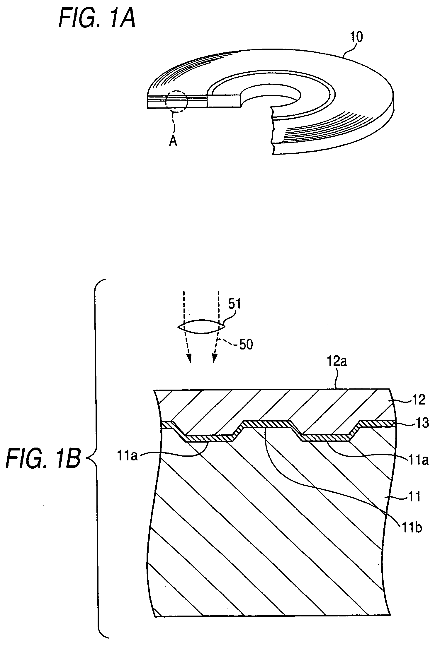
[0067] A test sample identical in structure to the optical recording medium 10 shown in FIG. 1 was fabricated according to the following method.

[0068] First, an injection molding process was performed to form a disc-shaped base substrate 11 made of polycarbonate having a thickness of about 1.1 mm and a diameter of about 120 mm and having lands 11a and grooves 11b formed thereon. The depth of the grooves 11b was set at about 21 nm, and the width of the grooves 11b was set at about 169 nm. The track pitch was set at about 320 nm.

[0069] Next, the base substrate 11 was set in a sputtering apparatus to perform a sputtering process on the same, whereby a recording layer 13 having a thickness of 36 nm was formed on the side of the substrate having the lands 11a and the grooves 11b formed thereon using both of a ...


PUM

PropertyMeasurementUnit
wavelengthaaaaaaaaaa
thicknessaaaaaaaaaa
outer diameteraaaaaaaaaa

Abstract

When a space region shorter than the radius of a beam spot is formed, pre-heating with an assist pulse is not performed, and an off pulse pattern is fixed at a base power level. When a space region longer than the radius of the beam spot and shorter than the diameter of the beam spot is formed, an assist pulse is applied to the end of the space region to be formed. The length of the assist pulse is made greater, the longer the space region to be formed. Further, when a space region longer than the diameter of the beam spot is formed, an assist pulse is applied to the end of the space region to be formed, and the length of the assist pulse is kept constant regardless of the length of the space region to be formed.

Description

BACKGROUND OF THE INVENTION [0001] The present invention relates to a method of recording information on an optical recording medium and, particularly, to a method of recording information on a write-once type optical recording medium. The invention also relates to an information recording apparatus for recording information on an optical recording medium and, particularly, to an information recording apparatus for recording information on a write-once type optical recording medium. [0002] Recently, proposals have been made on next-generation optical media having a recording capacity much greater than that of media in the related art and allowing a very high data transfer rate to be achieved, and some of such media have already been put in practical use (see Patent Document 1). Unlike optical recording media in the related art, recording and reproduction of data in and from such a next-generation optical media is performed using a laser beam having a wavelength of about 405 nm and a...

Claims


Application Information

Patent Timeline
Patent Type & Authority Applications(United States)
IPC IPC(8): G11B7/00G11B7/0045G11B7/125
CPCG11B7/00456
Inventor KOBAYASHI, TATSUHIROMISHIMA, KOJI
Owner TDK CORPARATION
Why Eureka
Try Eureka