
Help system for implanting a hip prosthesis on an individual

a technology for hip prosthesis and individual, applied in the field of total hip prosthesis implanting, can solve the problems of limited use, insufficient technique in practice, and relatively complex operation of implantation of prosthesis by surgeon, and achieve the effect of relatively simple measurement and calculation

Inactive Publication Date: 2009-12-24
UNIV DE BRETAGNE OCCIDENTALE
View PDF10 Cites 27 Cited by
  • Summary
  • Abstract
  • Description
  • Claims
  • Application Information

AI Technical Summary

Benefits of technology

[0022]Thus, an aspect of the disclosure is based on a new and inventive approach that takes several reference positions into account so as to optimize the placement of the total hip prosthesis, to reduce the risks of dislocation and to restore proper leg length.
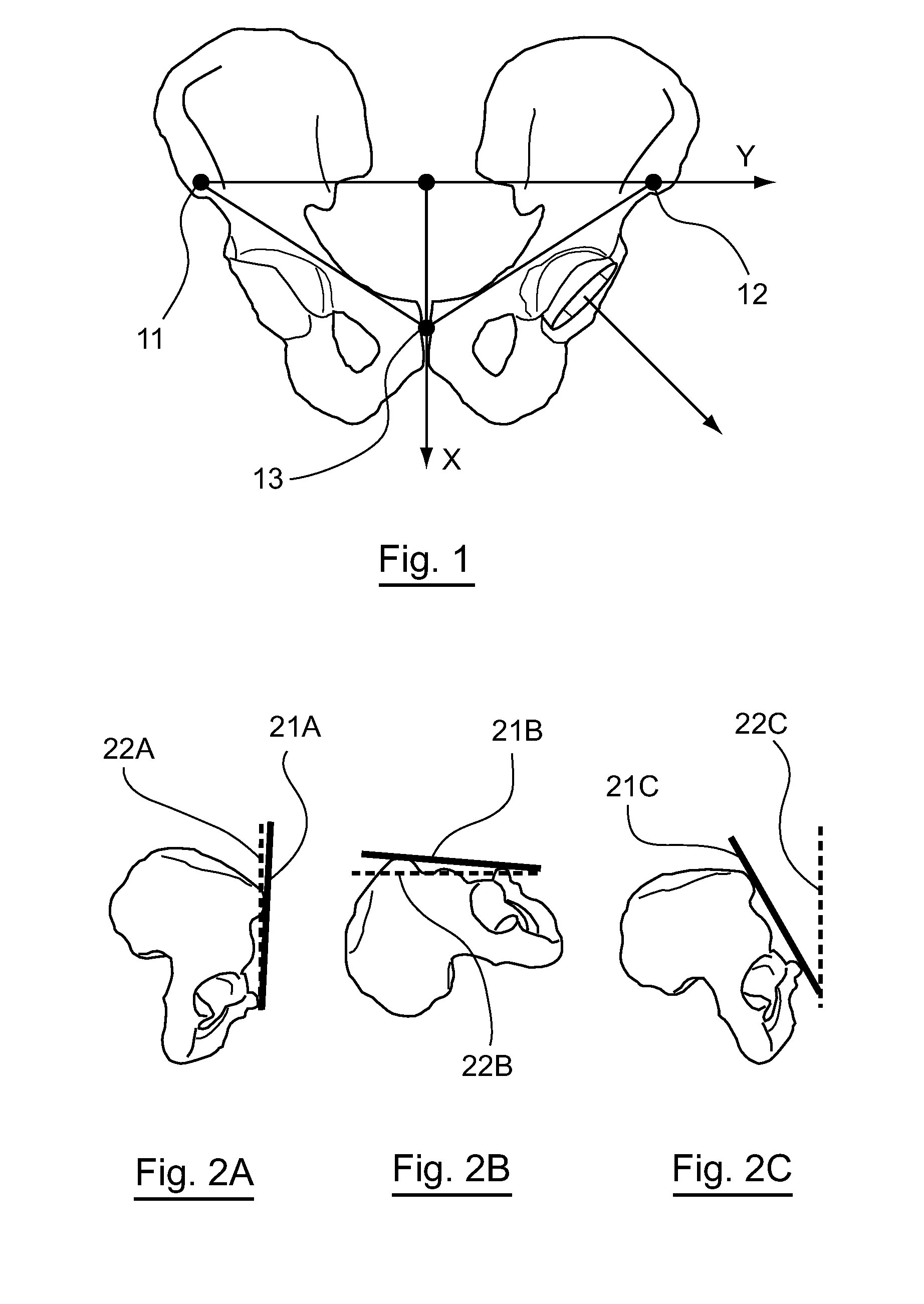
[0038]In fact, the inventors have detected that prosthetic impingement circles are sometimes inaccurate, and include positions that are anatomically not acceptable. An aspect of the disclosure thus proposes correcting these circles, to issue anatomical impingement circles, so as to further reduce the risks of poor prosthesis placement, and thus dislocation.
[0040]The measurements and calculations are thus relatively simple and fast.

Problems solved by technology

Implantation of a prosthesis by a surgeon is a relatively complex operation, since the femoral part and the acetabulum even more so, must be placed in an optimized manner, particularly to prevent the prosthesis from dislocating during high amplitude movements.
This result is effective but presents the disadvantage of significant complexity (tomography, computerized simulation, etc.) that limits its use, particularly for reasons of cost.
However, this technique may turn out to be insufficient in practice, since the measurements are performed during surgery, and the individual is put to sleep in a particular position (recumbent position).
By consulting the different circles, the practitioner may retain the position of the prosthesis corresponding to the best compromise, while, according to known techniques, he would optimize this position for only the recumbent position, which may lead to aberrations in other positions.
In fact, the inventors have detected that prosthetic impingement circles are sometimes inaccurate, and include positions that are anatomically not acceptable.

Method used


Image

  • Help system for implanting a hip prosthesis on an individual
  • Help system for implanting a hip prosthesis on an individual
  • Help system for implanting a hip prosthesis on an individual

Examples


Embodiment Construction

1. Introduction

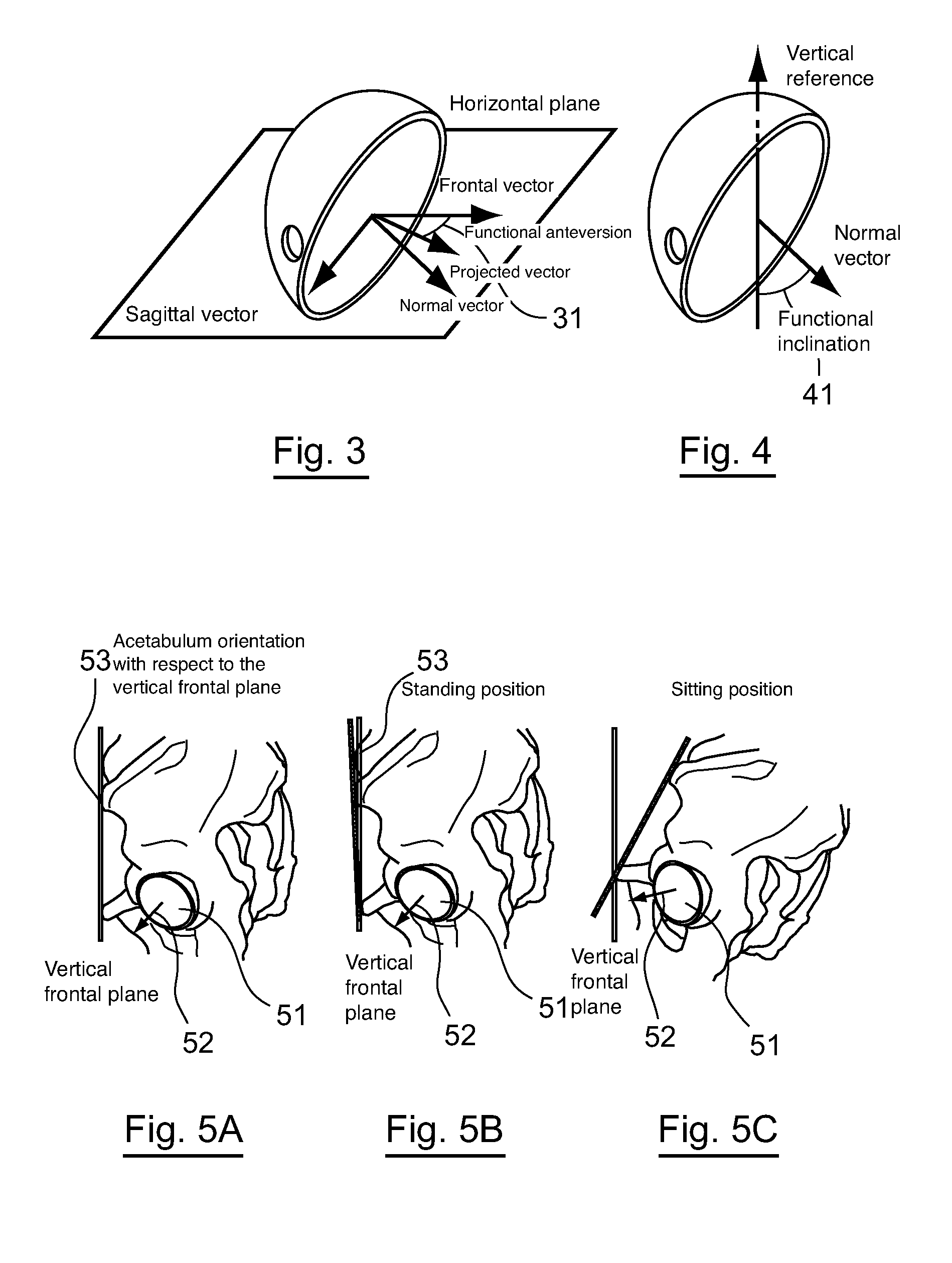
[0080]The inventors of the present disclosure have observed that an implantation under the conditions described above in the Background section is often not optimal, since it only takes this particular position, the recumbent position, into account, and not other possible positions, in particular standing and sitting positions.

[0081]However, it appears that an optimal position in the recumbent position may not be optimal in the sitting or standing position.

[0082]In other words, collisions between the prosthesis and the acetabulum may be produced, likely to lead to a dislocation, in certain situations, even when the acetabulum was placed optimally with relation to the anterior pelvic plane determined in the recumbent position.

[0083]One of the main constraints for positioning a total hip prosthesis is thus to optimize the position and orientation of the implant, in order to prevent postoperative instabilities. To do this, a frame of reference, known as the Lewinneck pla...


PUM


Abstract

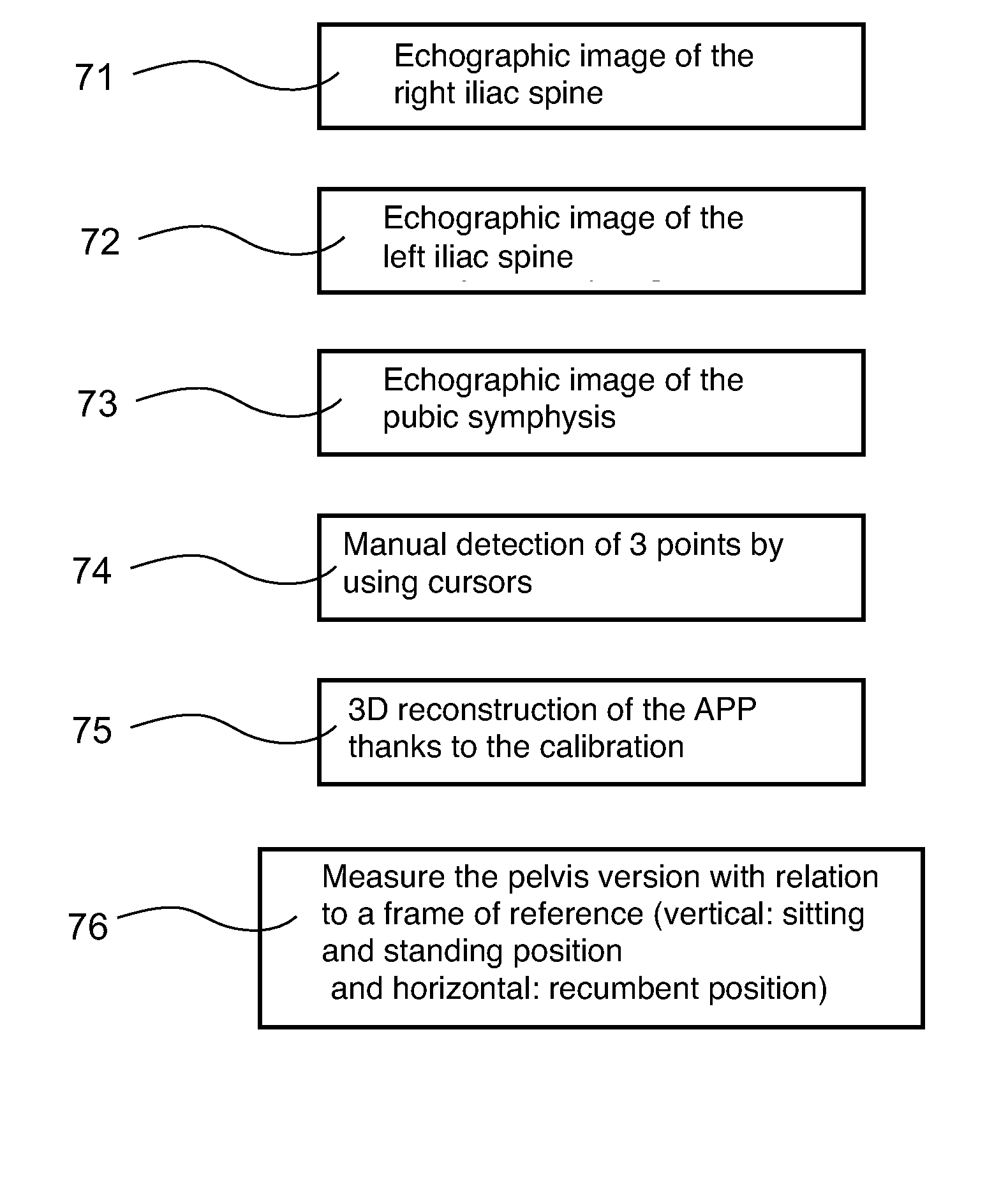
A system and method are provided for helping implant a hip prosthesis in an individual, which includes an acetabulum intended to be placed in the hip bone of the patient and a femoral part intended to be integrally connected to the femur of the individual. The method includes: obtaining, before the operation, images issued by a device that images a human body and locates a position of images in space. The images are taken in at least three reference positions: standing; recumbent; and sitting. Before the operation, the method determines a pelvis version of the individual in different positions by analyzing the images. During the operation, the method measures a position of the acetabulum with relation to the pelvis of the individual, and simultaneously restores information representative of prosthetic mobility of the hip with relation to each of the reference positions, for a current position of the acetabulum.

Description

CROSS-REFERENCE TO RELATED APPLICATIONS[0001]The present application is based on and claims the benefit of U.S. Provisional Patent Application No. 61 / 074,328, filed Jun. 20, 2008, the content of which is hereby incorporated by reference in its entirety.STATEMENT REGARDING FEDERALLY SPONSORED RESEARCH OR DEVELOPMENT[0002]None.THE NAMES OF PARTIES TO A JOINT RESEARCH AGREEMENT[0003]None.FIELD OF THE DISCLOSURE[0004]The field of the disclosure is that of implanting total hip prostheses. More precisely, the disclosure relates to a computerized system enabling optimized placement of the constituent elements of such a prosthesis on an individual.BACKGROUND OF THE DISCLOSURE[0005]A total hip prosthesis generally includes two parts: a first part integrally connected to the femur, known as the femoral part comprising a rod introduced in the femur, equipped with an essentially spherical head, and an acetabulum provided to receive the femoral head. The acetabulum, also known as a cup when it i...

Claims


Application Information

Patent Timeline
IPC IPC(8): G06T7/00A61F2/32
CPCA61B2019/505A61F2/34A61F2/4657G06T2210/41A61F2002/4668G06T19/00A61F2002/4632A61B2034/105
Inventor DARDENNE, GUILLAUMESTINDEL, ERICHAMITOUCHE, CHAFIAAROUX, CHRISTIAN
Owner UNIV DE BRETAGNE OCCIDENTALE
Learn More