Method for compensating length of differential pair and method for calculating compensation length thereof and computer accessible storage media

Inactive Publication Date: 2009-08-13
INVENTEC CORP
View PDF4 Cites 30 Cited by
  • Summary
  • Abstract
  • Description
  • Claims
  • Application Information

AI Technical Summary

Benefits of technology

[0007]Accordingly, the present invention is directed to a method for calculating compensation length of a zigzagging t

Problems solved by technology

With the progressing of the technology, working frequencies of digital circuits are increasing, thus many undesired electromagnetic effects are generated.
In the existing digital circuit, unit density of elements is increasing continuously, thus many challenges are encountered in circuit design of PCB.
A phase skew caused by

Method used


Image

  • Method for compensating length of differential pair and method for calculating compensation length thereof and computer accessible storage media
  • Method for compensating length of differential pair and method for calculating compensation length thereof and computer accessible storage media
  • Method for compensating length of differential pair and method for calculating compensation length thereof and computer accessible storage media

Examples

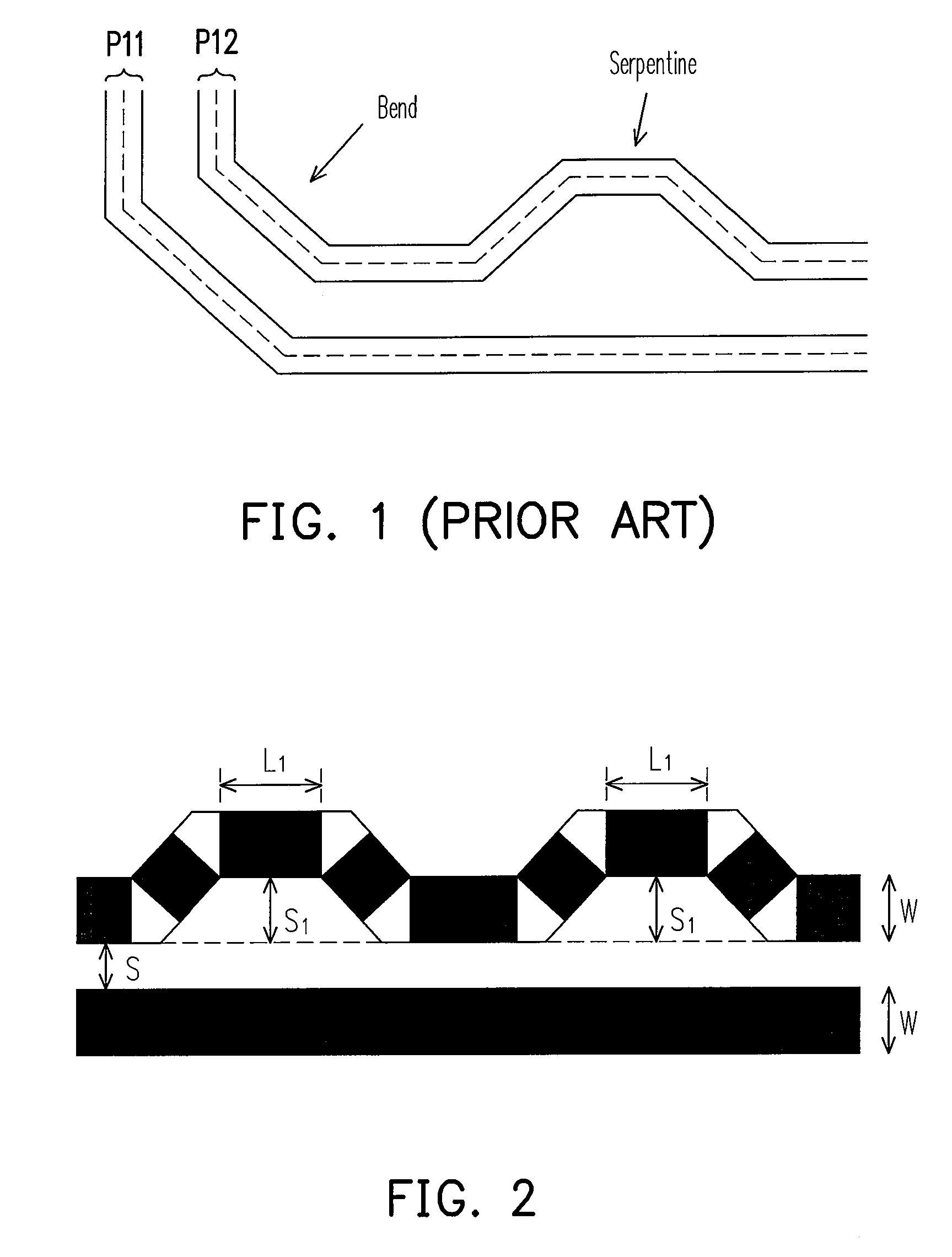
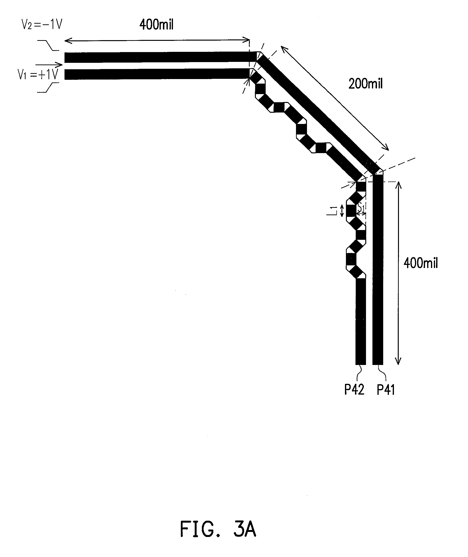

Example

[0025]Reference will now be made in detail to the present embodiments of the invention, examples of which are illustrated in the accompanying drawings. Wherever possible, the same reference numbers are used in the drawings and the description to refer to the same or like parts.

[0026]The following embodiments will be provided to illustrate the present invention. Those of ordinary skill in the art can understand and implement the present invention according to the embodiments. Definitely, the embodiments can also be implemented in the manner of a computer program, and the computer program is stored in a computer accessible storage media, such that the computer executes the following methods.

[0027]In the following embodiments, the zigzagging type delay line is implemented as a serpentine. This embodiment analyzes the actual current trend to deduce a more accurate equation, so as to accurately calculate the compensation length of actual signal path in the zigzagging type delay line, the...


PUM


Abstract

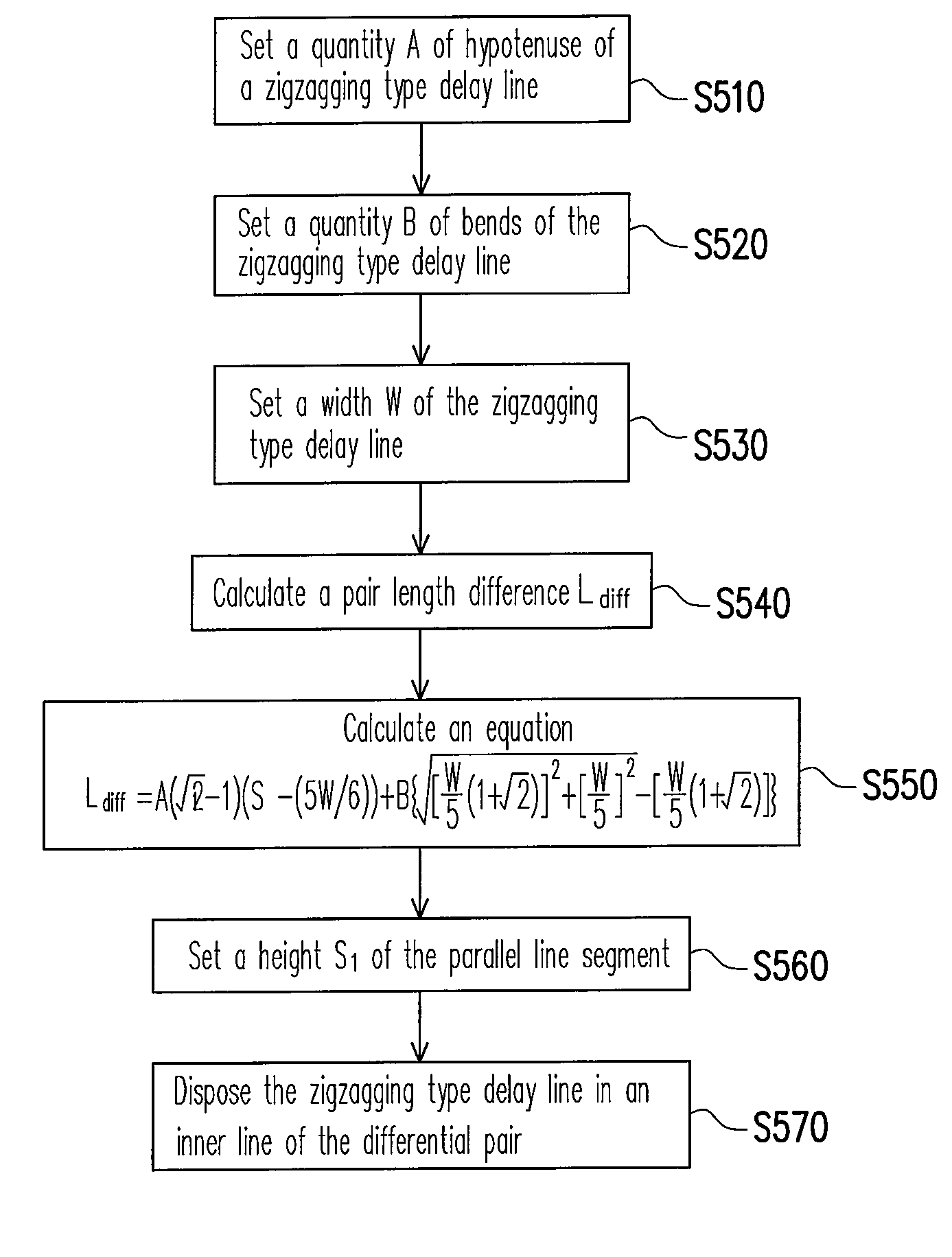
A method for compensating length of differential pair and a method for calculating compensation length of the zigzagging type delay line thereof are provided. The method for calculating compensation length of the zigzagging type delay line includes following steps. The quantity A of hypotenuse and the quantity B of bends of the zigzagging type delay line are counted. The width W of the zigzagging type delay line is measured. The height S1 of the parallel line segment of the zigzagging type delay line is measured. An equation
Ldiff=A(2-1)(S1-(5W/6))+B{[W5(1+2)]2+[W5]2-[W5(1+2)]}
is calculated for calculating the compensation length Ldiff of the zigzagging type delay line.

Description

BACKGROUND OF THE INVENTION[0001]1. Field of the Invention[0002]The present invention generally relates to a circuit layout, in particular, to a method for compensating length of differential pair and a method for calculating compensation length of a zigzagging type delay line.[0003]2. Description of Related Art[0004]With the progressing of the technology, working frequencies of digital circuits are increasing, thus many undesired electromagnetic effects are generated. Taking a printed circuit board (PCB) as an example, when a signal is transmitted on a transmission line, as an electromagnetic wave is transmitted outward through a medium, an electromagnetic radiation is generated. The electromagnetic radiation affects the normal operation of other electronic elements, which is the so-called electromagnetic interference (EMI). In the existing digital circuit, unit density of elements is increasing continuously, thus many challenges are encountered in circuit design of PCB. In actuall...

Claims


Application Information

Patent Timeline
IPC IPC(8): G06F17/50
CPCG06F17/5036H05K1/0245H05K2201/09263H05K3/0005H05K2201/09236H05K1/0248G06F30/367
Inventor LIN, YU-SEN
Owner INVENTEC CORP
Why Eureka
Try Eureka